- ページ 3
コントロールユニット Dantel A11-46017-01のPDF インストレーション&オペレーションマニュアルをオンラインで閲覧またはダウンロードできます。Dantel A11-46017-01 16 ページ。 Summary audible alarm module

CIRCUIT DESCRIPTION
T
A - R
C
ABLE
ELAY
OILS
RELAY COILS
K1 AND K2
Activated by Alarm Group 1.
K3 AND K4
Activated by Alarm Group 2.
K1 AND K3
Activated by a new alarm.
K2 AND K4
Activated by an existing
alarm.
46017-0398 <90-00006>
A
functional schematic for the 46017 Summary Audible
Alarm Module is shown in Fig. 1. Here is a brief description
of each of the functional parts of the circuit:
Input Latching Circuits
There are 16 alarm input circuits. Each one has an input latch-
ing circuit that remains inactive with a high state present until
an alarm is indicated (when an input goes to ground). When an
alarm occurs, even momentarily, the input latch circuit holds
(latches) its output to the alarm summing logic.
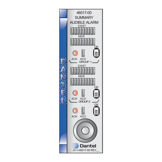
When an alarm comes in, two front panel LEDs light. The LED
labeled EXIST follows the input signal, but the NEW LED is
held by the latch circuit until someone acknowledges the alarm.
When alarms are acknowledged, the NEW LEDs go out. There
are four ways to acknowledge alarms:
♦
Push the front panel acknowledge (ACK) buttons in factory-
wired applications. Pins 27 and 41 for Alarm Group 1, and
pins 15 and 28 for Alarm Group 2 are normally wired to-
gether at the factory to enable the buttons to operate.
♦
Connect pin 41 for Alarm Group 1 and pin 15 for Alarm
Group 2 to a remote ground source.
♦
Connect pin 29 of the EXT ACK to ground. Connect pin 31 to
pins 41 and 15 of 46017 modules. Pressing the EXT ACK
button will acknowledge alarms on the 46017 SAAM and all
modules to which the switch is wired.
♦
Set the DIP switches to acknowledge alarms automatically
after a certain time-out period (refer to Table A).
Alarm OR'd Logic
There are two groups of eight inputs combined by the alarm
logic circuit (called alarm OR'd logic). One or more inputs results
in an output to the relay select and driver circuits.
If an alarm signal is present at the alarm OR'd logic and another
alarm signal from the same group comes in, its front panel
LED lights to indicate the additional alarm. The audio alarm
tone rate does not change. However, if the first alarm is from
Group 1 and the second is from Group 2, the Group 2 alarm
takes precedence over the Group 1 alarm. In that case, the audio
alarm rate changes and the device generates a different tone.
Relay Select and Driver Circuit
The alarm signal from each group's OR'd logic goes to the relay
select and driver circuit to activate relays. Each relay coil
operates two sets of form-C contacts. Refer to Table A.
The NEW relays deactivate when you acknowledge an alarm.
The EXIST relays follow the alarm input. If alarms still exist
when they are acknowledged, the NEW relays deactivate but the
EXIST relays do not.
P
3
AGE
