- ページ 16
エア・ハンドラー Dantherm VA-M40 MKIIのPDF サービスマニュアルをオンラインで閲覧またはダウンロードできます。Dantherm VA-M40 MKII 20 ページ。
Control system
Control system
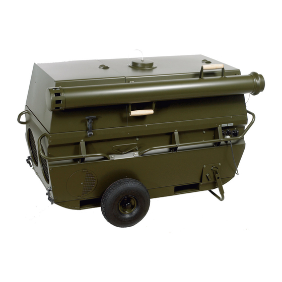
Illustration, outside This illustrates the control panel which is placed on the left hand side of the unit when
Illustration, inside
16
The heater incorporates a control system that allows fully automatic operation after a
start cycle has been initiated by the room thermostat. Safety devices will completely
shut down ignition, fuel flow and fans in case of malfunction. All operating controls and
components are mounted to permit easy access for operation, maintenance and trou-
bleshooting.
Details about how to operate the unit is to be found in section "Operation of the heater",
page 27.
standing in front of the burner compartment:
Fig. 5
This illustrates the control panel which it is possible to see on the left hand side, after
opening the burner compartment cover:
Fig. 6
No.
Connector for remote thermostat
Connector for CO monitoring
Function switch
See details on the different posi-
tions in section "Operation of the
heater", page 27
Power supply cable
No.
LED lights which indicate the dif-
ferent states of the unit. These are
explained in section "Operation of
the heater", page 27
Hour-meter which accumulate the
hours the burner is active
Reset button for circuit breaker
which protects the control printed
circuit board
Part
Part
Continued overleaf