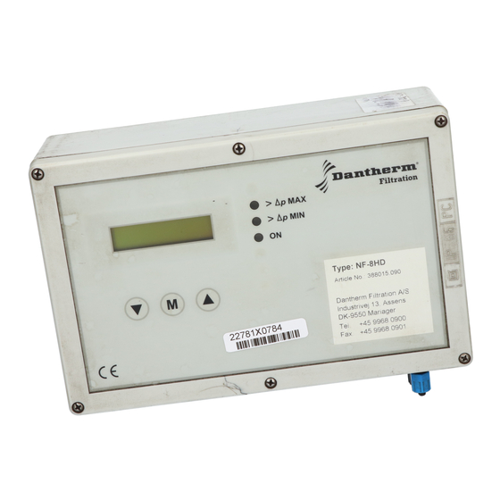
01AUG 1005GB
Final inspection after installation.
• Check that the circuit voltage is 230V AC 50-60 Hz.
• Monitoring of valve and unit function by starting the test operation.
• The down-time-cleaning procedure is tested by briefly opening and closing the terminals
E1 and E2 (first select DTC mode 1)
• The pressure difference action can be tested or simulated. By squeezing the top hose (in-
side the control box) with the fingers until the text indicates an increasing pressure, its ef-
fect can be simulated. When
When the pressure sinks below
MAX is once again exceeded.
• Check whether the covers on the electrical controllers are properly and tightly mounted.
Specifications
Application
Mains voltage
Output voltage
Signal input
Signal output
Outputs for valves
Output for extension unit
Optional output F1, F2
∆
p-range
Sensor
Fuse
Temperature range
Protection
Dimensions
Weight
Mounting height
∆p
-MAX is exceeded the cleaning procedure is activated.
∆p
-MIN , the cleaning procedure is stopped until Delta p-
Specifications
230 V AC +/-10%
110 V ... 120 V AC +/-10%
Approx. 24 V DC
24 V DC, potentialfree operation
Relay-output, max. 2 A, 250 V
or 1 A, 30 V DC
1 ... 16, 24 V / DC, expansible to 160 outputs,
Output power 42 Watt
Supply voltage and puls wire connection to the
extension units
4 ... 20 mA; 0 ... 5000 Pa;
internal resistance 500 Ω
No earth connection to the 4-20-mA-Signal
0 ... 5000 Pa
Piezoelectrically secured against positive pres-
sure until 120 kPa
0,4 A / T, 5 x 20 mm, 250 V
-20°C to + 60°C
Housing IP65
W x H x D 250 x 160 x 90 mm
ca. 0,8 kg
max. 3000 m N.N.
Cat.20 / Tab. 05.91 / Page 05.07
Terminals
1, 3
2, 3
15 - 29 and
37 - 51
10 - 13
5 - 9
14 - 28 and
36 - 50
30 - 33
34, 35
