- ページ 13
アクセサリー 4B HTAS1V34のPDF 操作マニュアルをオンラインで閲覧またはダウンロードできます。4B HTAS1V34 20 ページ。 Wda sensor belt alignment / motion & broken / slack chain monitor

SCREW CONVEYOR -
For speed monitoring on a screw conveyor, the sensor will need to detect a ferrous steel flight (target).
If the housing is mild steel, cut a 4 inch or larger diameter hole in the housing and weld a 300 series
stainless steel plate over the hole. Make sure that the plate is larger than the WDA's mounting bracket,
and mount the WDA sensor to the stainless steel plate. The sensor should be mounted 1-3 inches away
from the edge of the hole in the housing or it may detect the mild steel as a false target. Since 300
series stainless steel is non-ferrous, the sensor will not be affected as the sensing field can pass through
the plate.
If the housing is 300 series stainless steel, no hole is required, mount the WDA3 sensor directly to
the housing. The sensor should be mounted 1-3 inches away from the moving ferrous flight (target)
but over 3 inches away from the rotating shaft. This installation is very similar to option 1 for drag
conveyors.
Figure 8 -
WDA Sensor Detecting
Screw Flight (Pulse)
DRAG CONVEYOR -
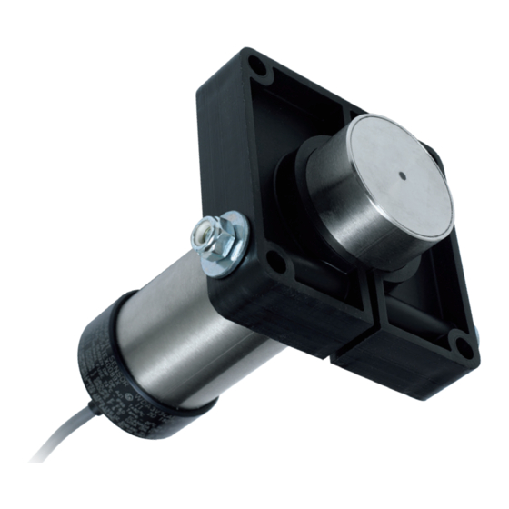
For slack/broken chain detection on drag conveyors, the WDA sensor can be installed using one of
three options (see below). Either a hole can be cut in the conveyor housing for the sensor, or the mount
can be installed on a stainless steel plate welded directly to the conveyor housing over the hole. Since
stainless steel is non-ferrous, the sensor will not be affected as the sensing field can pass through the
plate.
Once the proper placement has been identified, cut a 2-1/4 inch (57 mm) diameter hole in the drag conveyor
housing for each sensor. If using stainless steel plate, the hole diameter may need to be larger.
The WDA sensor can be mounted using one of the following three methods -
1. Drill and tap the machine casing for 5/16 inch threaded bolts. Make sure that the bolts used to
secure the sensor mounting bracket are short enough that they do not interfere with the operation of
the machine.
2. Use threaded rivet nuts for 5/16 inch threads. The length of the rivet nut will depend on the thickness
of t he machine's casing. Make sure that the bolts used to secure the sensor mounting bracket are
short enough t hat they do not interfere with the operation of the machine.
3. CD weld 5/16 inch threaded welding studs to the machine casing.
To drill the four 5/16 inch bolt holes for the sensor mounting bracket, use the supplied paper template from
the sensor manual or use the bracket itself, by centering on the existing 2-1/4 inch (57 mm) hole.
INSTALLATION - CONVEYORS
PAGE 13
PULSE
To Speed Relay
Speed Relay
(SR2V5-1)
