- ページ 2
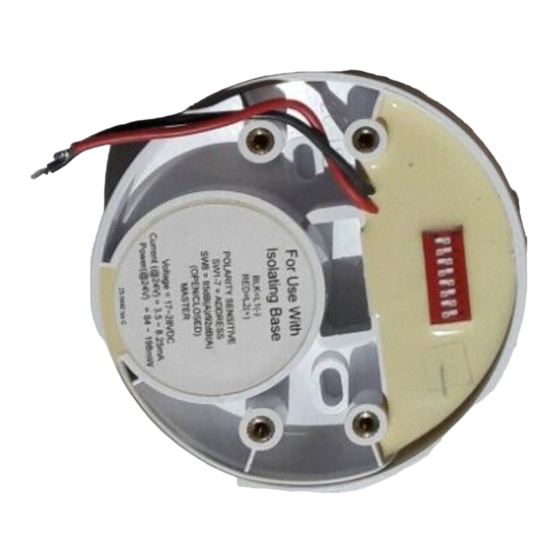
舶用機器 Apollo 45681-266のPDF インストレーション・マニュアルをオンラインで閲覧またはダウンロードできます。Apollo 45681-266 2 ページ。 Intelligent base sounder for use with isolating bases
Technical data
Operating voltage
Sounder output
switch selectable 85 or 92dB(A)
SPL polar plot data is available in document
M04-002, available on request.
Current consumption at 24V DC
quiescent
switch-on surge
sounder operated at 85dB(A)
sounder operated at 92dB(A)
IP rating
The maximum number of Intelligent Base Sounders permitted between standard XP95 isolators
(part no. 55000-720) or isolating bases (part no. 45681-321/284) is 20, depending on the loop
loading. Apollo's Loop Calculator is a program available as a free download from www.apollo-
fi re.co.uk and can be used to check the loading of any proposed loop design.
L2
Loop
wiring
IN
Fig 1 Connecting diagram
17—28V DC
300μA
1.2mA for 1 sec
3.5mA
8.25mA
21C
Black
flying
Functional
lead
Earth or
screen
L1
Isolating Base (45681-321)
Red
flying
lead
Intelligent Sounder (45681-266)
Loop
wiring
OUT
© Apollo Fire Detectors Limited J.Roughton 2003
Address and Sound Output Setting
The address of the base sounder is set using seven segments of the eight-segment DIL switch
(Fig 2). Segments 1-7 of the switch are set to "1" or "0" (ON), using a small screwdriver or similar
tool. A complete list of address settings is shown below.
The eighth seg ment selects the sound output level, 85dB or 92dB (ON).
DIL switch
DIL switch
setting
setting
addr
1234567
addr
1234567
addr
1
1000000
11
1101000
2
0100000
12
0011000
3
1100000
13
1011000
4
0010000
14
0111000
5
1010000
15
1111000
6
0110000
16
0000100
7
1110000
17
1000100
8
0001000
18
0100100
9
1001000
19
1100100
10
0101000
20
0010100
51
1100110
61
1011110
52
0010110
62
0111110
53
1010110
63
1111110
54
0110110
64
0000001
55
1110110
65
1000001
56
0001110
66
0100001
57
1001110
67
1100001
58
0101110
68
0010001
59
1101110
69
1010001
60
0011110
70
0110001
101
1010011
106
0101011
111
102
0110011
107
1101011
112
103
1110011
108
0011011
113
104
0001011
109
1011011
114
105
1001011
110
0111011
115
Example of address and output setting
Address shown is 78 with a sound out put of 85dB se lect ed.
Example:
Individual
Address 78 =
0
O
ON = 0
1
N
Individual Address
Fig 2
DIL switch
DIL switch
setting
setting
1234567
addr
1234567
addr
21
1010100
31
1111100
41
22
0110100
32
0000010
42
23
1110100
33
1000010
43
24
0001100
34
0100010
44
25
1001100
35
1100010
45
26
0101100
36
0010010
46
27
1101100
37
1010010
47
28
0011100
38
0110010
48
29
1011100
39
1110010
49
30
0111100
40
0001010
50
71
1110001
81
1000101
91
72
0001001
82
0100101
92
73
1001001
83
1100101
93
74
0101001
84
0010101
94
75
1101001
85
1010101
95
76
0011001
86
0110101
96
77
1011001
87
1110101
97
78
0111001
88
0001101
98
79
1111001
89
1001101
99
80
0000101
90
0101101
100
1111011
116
0010111
121
0000111
117
1010111
122
1000111
118
0110111
123
0100111
119
1110111
124
1100111
120
0001111
125
126
Volume
85dB =
1
1
1
0
0
1
1
2
3
4
5
6
7
8
Switch
Vol
© Apollo Fire Detectors Limited 2006-9/JDR/TP
DIL switch
setting
1234567
1001010
0101010
1101010
0011010
1011010
0111010
1111010
0000110
1000110
0100110
1101101
0011101
1011101
0111101
1111101
0000011
1000011
0100011
1100011
0010011
1001111
0101111
1101111
0011111
1011111
0111111