- ページ 7
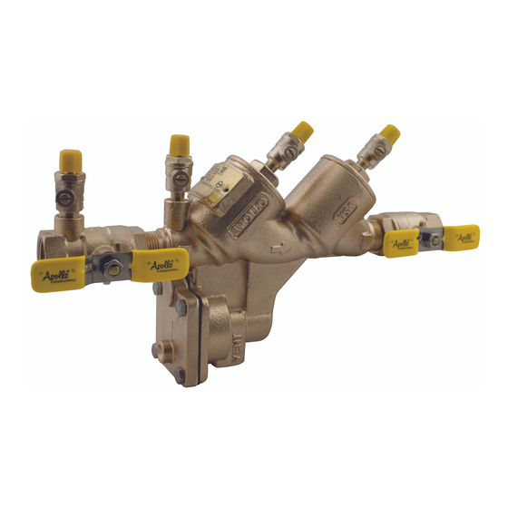
コントロールユニット Apollo Valves RP4AのPDF インストレーション、オペレーション、メンテナンスマニュアルをオンラインで閲覧またはダウンロードできます。Apollo Valves RP4A 16 ページ。 Reduced pressure principle (rp) backflow preventer

F.
Assembly - Relief Valve
1.
Apply a thin coat of Apollo lubricant, DOW® 111 or equal on o-rings before installing.
2.
Install o-ring on RV seat. Line up the seat with the bore and push rmly into place.
3.
If the RV stem has been disassembled, install o-ring onto RV stem.
4.
Slide bushing over RV stem and position spring onto bushing. Note the correct position of the bushing from step #6 in
disassembly instructions. (Spring must t over the smaller shoulder of the bushing upon reassembly.)
5.
Position diaphragm plate and compress spring, install screw into RV stem.
6.
Turn the assembly over and install seat disc (and retaining washer on 1-1/4", 1-1/2", & 2" models only), and screw.
7.
Install o-ring onto bushing.
8.
Slide complete assembly onto the body.
9.
Position diaphragm over ange, install cover, and tighten bolts evenly.
10. Open #1 shut-o valve and bleed air out of the unit through #2, #3, and #4 test cocks; then open #2 shut-o valve.
11. Test complete assembly to ensure proper operation.
V. TESTING PROCEDURES
NOTE: This is a 3 valve test kit procedure and may or may not be approved in all jurisdictions. Consult your local water purveyor
for acceptable test procedures.
Test Setup
1.
Notify customer water will be o ; inspect device for leaks, verify the make, model, and serial number.
2.
Flush test cocks, in order (4-1-2-3), (open #2 test cock very slowly to prevent accidental opening of the relief valve), then install
appropriate adapters (if necessary)
3.
Close valves "A", "B", & "C" on test kit and close the #2 shut-o valve.
4.
Connect high side hose to test cock #2, and low hose to test cock #3.
5.
Slowly open test cock #3, then open vent "C" valve and low "B" valve. This will bleed air from low side of gauge. Slowly open
test cock #2, then open high "A" valve. This will bleed air from high side of gauge. Close valve "A", then valve "B", then valve "C".
6.
Observe this apparent di erential pressure for check valve #1; this value must be at least 5.0 psi or greater.
TEST NO. 1
PURPOSE: To test check valve #2 against back pressure.
1.
Connect the vent "C" hose to test cock #4.
2.
Slowly open the high "A" and vent "C" valves and keep the low "B" closed.
3.
Open test cock #4.
4.
Gauge may decrease slightly due to disc compression. If pressure di erential continues to decrease until the vent opens,
then check valve #2 is reported as leaking.
TEST NO. 2
PURPOSE: To test shut-o valve #2 for tightness.
1.
After passing test No. 1, continue to test No. 2 by closing test cock #2.
2.
The indicated pressure di erential will decrease slightly. If pressure di erential continues to decrease (approaching zero) the
No. 2 shut-o valve is reported to be leaking.
Customer Service (704) 841-6000
www.apollovalves.com
BFMM RP4A SBF
7
