- ページ 12
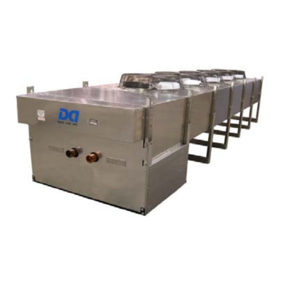
アクセサリー Data Aire DAFCのPDF マニュアルとユーザーマニュアルをオンラインで閲覧またはダウンロードできます。Data Aire DAFC 20 ページ。 Fluid coolers
Inspection
This Data Aire unit has been factory run-tested and passed a comprehensive inspection
prior to its packaging and shipment to ensure that it arrives in excellent condition. However,
shipping damage can occur and a visual inspection of the outer crating immediately upon
delivery should be performed.
Note any external damage or other transportation damage on the freight carrier's forms.
Inspect the unit itself for internal damage. A claim should be filed with the shipping company
if the equipment is damaged or incomplete.
Loose items such as remote control panels, disconnect switch handles, or other items are
packed inside the unit. Refer to the yellow shipping tag located on the unit door for details.
Freight damage claims are the responsibility of the purchaser. Action to recover
losses should be filed immediately. Please notify factory personnel of any claims.
Location
Remote heat exchangers must be located in an area that will ensure free air flow into and
out of the unit plus adequate service clearance. The unit should not be placed any closer
than 36" from any wall, with no more than two walls, or other obstruction.
With proper clearance on all other sides, two units can be placed side by side. Additional
units should be placed no closer than 48" apart.
Leg Assembly
The legs must be unbolted from their collapsed shipping position and extended prior to
placing the unit on its pad. Each leg extends down approximately 18" and reattaches using
the same bolts (see detail "A-A", drawing entitled Fluid Coolers DAFC Model 05-50 on page
14). Note: Failure to extend the legs will result in poor air distribution over the cooling coil
resulting in significant capacity reduction.
Concrete pads are often used to provide support for the heat exchanger when set on the
ground. Bolt holes in the bottom of each leg can be used to anchor the unit. Units mounted
on a roof should be placed on rails designed to distribute the unit's weight. Standard practices
and local codes should be followed in either instance.
Rigging
The heat exchanger should be moved to its (typically rooftop) mounting location using a
crane or fork lift. Each fan section has heavy, steel leg supports with lifting holes at the top.
Do not lift with a choke sling around the unit. Spreader bars are recommended for lifting
multiple fan units. Under no circumstances should the coil headers or piping be used for
lifting the unit. Ideally, the unit should be kept in its shipping crate until it is ready to be set in
place.
(See drawing on next page.)
Installation and Maintenance
12