- ページ 7
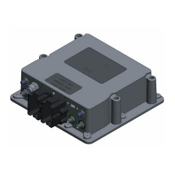
ゲートウェイ Appareo 608065-000043のPDF インストレーション・マニュアルをオンラインで閲覧またはダウンロードできます。Appareo 608065-000043 11 ページ。

3.2. INSTALLATION INSTRUCTIONS
Install the gateway and antennas using the following steps:
1. Find an installation location for the gateway that meets these specifications:
REQUIRED:
•
Meets the spacing requirements in Table 4.
•
Connectors point downward or sideways/horizontal (not up).
•
Avoid areas of moving parts or debris. For example, don't mount it on the bottom of a
frame that may be covered in mud or brush against crop/brush underneath.
•
Avoid high temperature areas such as engine bays, near exhaust systems, or on
hydraulic manifolds.
•
Supports the preferred antenna locations in Step 2 (due to antenna cable length).
RECOMMENDED:
•
Connectors pointing downward.
•
Do not mount directly next to other RF antennas (such as cell, radio, or Wi-Fi).
•
Mount within line of sight of the operator to observe LED.
2. Find an installation location for the antennas that meet these specifications:
REQUIRED:
•
Meets the spacing requirements in Table 4.
•
Fins of the antennas are facing upward. The steel plate the antennas are mounted to
should be flat and be towards the bottom of the installation. Do not mount sideways
or upside down.
•
Antennas have line of sight to connected devices and sky.
•
Avoid mounting directly next to steel plates, tanks, or other structures. For example,
avoid mounting the antenna on the side wall of an air cart, spreader, or sprayer tank.
•
Avoid mounting directly next to other RF antennas.
•
Do not mount inside the cab.
•
Do not run antenna cables alongside other electrical harnessing, especially high
power circuits.
RECOMMENDED:
•
Mount GPS antenna as central on the machine as possible.
3. Mount the gateway enclosure to the cab with ¼" or 6-mm fasteners and a torque of 30
in-lbs.
4. Torque the antenna terminations to gateway RF SMA connectors with a torque spec of
8.5 +/- 2 in-lbs.
600840-000045, rev. 2.2
Gateway Installation Manual
Page 7 of 11
