- ページ 4
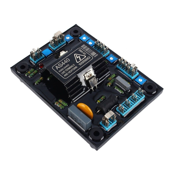
コントローラー Datacom AS440のPDF 仕様、取り付け、調整をオンラインで閲覧またはダウンロードできます。Datacom AS440 4 ページ。 Automatic voltage regulator (avr)

STABILITY ADJUSTMENT
The AVR includes a stability or damping circuit to provide
good steady state and transient performance of the
generator.
A switch is provided to change the response of the
stability circuit to suit different frame size generators and
applications. The table shows the options available.
The slo w response s e ttin g s may prove h e lp fu l in
re d u cin g lam p flicke r.
The correct setting of the Stability adjustment can be
found by running the generator at no load and slowly
turning
the stability control anti-clockwise
generator voltage starts to become unstable.
The optimum or critically damped position is slightly
clockwise from this point (i.e. where the machine volts
are stable but dose to the unstable region).
UNDER FREQUENCY ROLL OFF (UFRO)
ADJUSTMENT
The AVR incorporates an underspeed protection circuit
which gives a volts/Hz characteristic when the generator
speed falls below a presettable threshold known as the
"knee" point.
The red Light Emitting Diode (LED) gives indication that
the UFRO circuit is operating.
The UFRO adjustment is preset and sealed and only
requires the selection of 50/60Hz using the jum per link.
For optimum setting, the LED should illuminate as the
frequency falls just below nominal, i.e. 47Hz on a 50Hz
system or 57Hz on a 60Hz system.
DROOP ADJUSTMENT
Generators intended for parallel operation are fitted with
a quadrature droop C.T. which provides a power factor
dependent signal for the AVR. The C.T. is connected to
S1, S 2 o n the AVR.
The DROOP adjustment is normally preset in the works
to give 5% voltage droop at full load zero power factor.
Clockwise increases the amount of C.T. signal injected
into the AVR and increases the droop with lagging power
factor (cos 0 ). With the control fully anti-clockwise there
is no droop.
FITTING AND OPERATING
TRIM ADJUSTMENT
An analogue input (А1 A2) is provided to connect to a
Power Factor Controller or other devices. It is designed to
accept dc signals up to +/- 5 volts.
WARNINGl A n y devices conn ected to th is in p u t m ust
be fu lly flo a tin g and galva nically isola ted fro m ground,
w ith an in s u la tio n ca p a b ility o f 500 Vac.
observe th is c o u ld re su lt in e qu ipm e nt dam age.
The dc signal applied to this input adds to the AVR sensing
circuit. A1 is connected to the AVR 0 volts. Positive on A2
increases excitation. Negative on A2 decreases excitation.
until
the
The TRIM control allows the user to adjust the sensitivity of
the input.
applied signal has no effect. Clockwise it has maximum
effect.
Normal setting is fully clockwise when used with a Power
Factor Controller.
OVER EXCITATION (EXC TRIP) ADJUSTMENT
The adjustment is set and sealed in the works and should
not be altered.
An over excitation condition is indicated on the common
LED which also indicates under speed running.
The generator must be stopped to reset an over excitation
condition.
4 / 4 Page
W ith TRIM fully anti-clockwise the externally
Failure to
