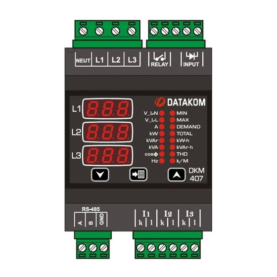
計測機器 Datakom DKM-407のPDF マニュアルをオンラインで閲覧またはダウンロードできます。Datakom DKM-407 4 ページ。 Din rail type network analyzer

DKM-407 DIN RAIL TYPE NETWORK
ANALYZER
The DKM-407 is a DIN rail mounted precision
unit allowing measurement and monitoring of
AC parameters of a distribution panel.
The unit is supplied between L1 and Neutral
terminals. Thanks to the supply range of 85-
305V, it is not affected by voltage fluctuations
and is capable of operating in any network.
The unit features an 32-bit ARM core
microcontroller. With a sampling rate of
4096s/s it reaches 0.5% precision.
The isolated RS-485 Modbus RTU port is not
affected by ground potential differences.
Program parameters may be uploaded from
PC.
Failure to follow below
instructions will result in
death or serious injury
Electrical equipment should be installed
only by qualified specialist. No responsibility
is assured by the manufacturer or any of its
subsidiaries for any consequences resulting
from the non-compliance to these
instructions.
Check the unit for cracks and damages due
to transportation. Do not install damaged
equipment.
Do not open the unit. There is no
serviceable parts inside.
Fuses of fast type (FF) with a maximum
rating of 6A must be connected to phase
voltage inputs, in close proximity of the unit.
Disconnect all power before working on
equipment.
When the unit is connected to the network
do not touch terminals.
Short circuit terminals of unused current
transformers.
Any electrical parameter applied to the
device must be in the range specified in the
user manual.
Verify correct terminal connections before
applying power.
SAFETY NOTICE
INSTALLATION
Before installation:
Read the user manual carefully, determine
the correct connection diagram.
Install the unit to the DIN rail.
Make electrical connections with plugs
removed from sockets, then place plugs to
their sockets.
Note that the power supply and measuring
circuits use common neutral.
Below conditions may damage the device:
Incorrect connections.
Incorrect power supply voltage.
Voltage at measuring terminals beyond
specified range.
Current at measuring terminals beyond
specified range.
Connecting or removing data terminals
when the unit is powered-up.
Overload or short circuit at relay outputs
Voltage applied to digital inputs over
specified range.
High voltage applied to communication port.
Below conditions may cause abnormal
operation:
Power supply voltage below minimum
acceptable level.
Power supply frequency out of limits
Phase order of voltage inputs not correct.
Current transformers not matching related
phases.
Current transformer polarity incorrect.
Detailed user manual of this product
may be downloaded at:
www.datakom.com.tr
