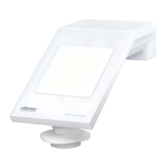
アクセサリー elsner elektronik P04i-WのPDF 技術仕様と設置手順をオンラインで閲覧またはダウンロードできます。elsner elektronik P04i-W 2 ページ。 Wind sensor

EN
P04i-W
Wind Sensor
Technical specifications and
installation instructions
Item number 30137
1.
Description
The Wind Sensor P04i-W records the wind-speed. The sensor is connected to the
control system WS1 or (KNX) WS1000 Color Style Connect via the P04i data recor-
der.
Functions:
•
Wind measurement: The wind strength is measured electronically and thus
noiselessly and reliably, even during hail, snow and sub-zero temperatures.
Even turbulent air and rising winds in the vicinity of the device are recorded
•
Suitable for: WS1 Color, WS1 Style, WS1000 Color, WS1000 Style,
KNX WS1000 Color, KNX WS1000 Style (each from software version 1.8) and
WS1000 Connect. Connection via P04i data collector
1.1. Deliverables
•
Wind sensor
•
Connection cable approx. 10 m, with plug and connecting terminals
•
Surface-mounted junction box (IP 55, not weatherproof)
•
Worm-thread clamp Ø 40-60 mm
•
4×50 mm stainless steel roundhead screws and 6×30 mm dowels for wall
mounting. Use fixing materials that are suitable for the base!
1.2. Accessories
•
P03/P04i data collector, No. 30132
1.3. Technical specifications
Housing
Plastic
Colour
White / Translucent
Assembly
Surface mount
Protection category
IP 44
Dimensions
approx. 62 × 75 × 155 (W × H × D, mm)
Weight
sensor with mount approx. 90 g.
total weight including accessories approx. 280 g
Ambient temperature
Operation -30...+50°C, Storage -30...+70°C
Voltage
24 V DC
Power
max. 20 mA
Wind sensor:
Measurement range
0 m/s ... 35 m/s
Resolution
0.1 m/s
Accuracy
±15% of the measured value for an incident flow of
45°...315° (frontal incident flow corresponds to 180°)
The product is compliant with the provisions of EU guidelines.
2.
Installation and commissioning
2.1. Installation notes
Installation, testing, operational start-up and troubleshooting should
only be performed by an electrician.
CAUTION!
Live voltage!
There are unprotected live components inside the device.
•
National legal regulations are to be followed.
•
Ensure that all lines to be assembled are free of voltage and take
precautions against accidental switching on.
•
Do not use the device if it is damaged.
•
Take the device or system out of service and secure it against
unintentional use, if it can be assumed, that risk-free operation is
no longer guaranteed.
The device is only to be used for the intended purpose described in this manual. Any
improper modification or failure to follow the operating instructions voids any and
all warranty and guarantee claims.
After unpacking the device, check it immediately for possible mechanical damage.
If it has been damaged in transport, inform the supplier immediately.
Wind Sensor P04i-W • Version: 25.06.2020 • Technical changes and errors excepted. • Elsner Elektronik GmbH • Sohlengrund 16 • 75395 Ostelsheim • Germany • www.elsner-elektronik.de • Technical Service: +49 (0) 7033 / 30945-250
Wind Sensor P04i-W
The device may only be used as a fixed-site installation; that means only when as-
sembled and after conclusion of all installation and operational start-up tasks and
only in the surroundings designated for it.
Elsner Elektronik is not liable for any changes in norms and standards which may
occur after publication of these operating instructions.
2.1.1. Installation location
Select an installation position on the building where the sensor can measure wind
without hindrance. Please ensure that the extended awning does not cast shade on
the unit, protects it against the wind.
At least 60 cm of clearance must be left around the device. This facilitates correct
wind speed measurement without eddies. This also prevents birds from biting it.
The wind sensor must not come into contact with water.
The installation position should prevent the wind sensor from being touched by
people.
90°
Wall
or
pole
2.1.2. Sensor position
1
ATTENTION!
Sensitive wind sensor.
•
Remove the protective transport sticker after installation.
•
Do not touch the sensor on the wind measuring element
(on bottom, recessed).
2.1.3. Attach mount
First, assemble the mount for wall/pole mounting. Release the screw joint of the
mount with a cross-headed screwdriver.
Wall installation
Hole spacing 30 mm
Fig. 1
There must be at least 60 cm clearance
to other elements (structures, cons-
truction parts, etc.) below, to the sides
and in front of the device.
60 cm
Fig. 2
The device must be attached to a ver-
tical wall (or a pole).
Place the supply line in a loop before
leading it into the wall or junction box.
This will allow rain to drip off and not
drain into the wall or box.
Fig. 3
The device must be mounted in the
Horizontal
cross direction, i.e. in horizontal
(transverse) direction.
Fig. 4
1 Wind measuring element
Fig. 5 Front view
Use two screws to attach the mount to
the wall. Use the fastening material
(dowels, screws) that is suitable for
the base.
Make sure that the arrows are pointing
upward.
1
