- ページ 2
コントローラー elsner elektronik 70531のPDF クイック・スタート・マニュアルをオンラインで閲覧またはダウンロードできます。elsner elektronik 70531 2 ページ。 Multifunctional actuators
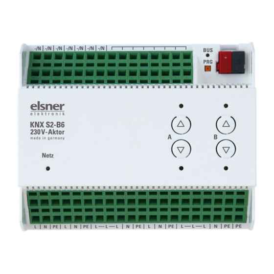
2.3.2. Device Design KNX S2-B6 230 V
The device is designed for series installation on mounting rails and occupies 6
width units.
1
2
3
5
7
6
8
9
10
11
14
12
13
1) –/N (bridged internally with terminal No. 5). When an external auxiliary voltage
is used (12...80 V DC, 12...240 V AC), one of the –/N terminals is to be assigned
with – or N
2) Free contacts (bridged internally)
3) Programming LED and programming buttons (PRG)
4) Bus terminal slot (KNX +/-)
5)
–/N (bridged internally with terminals No. 1)
6) Binary inputs 1-2 (two bridged connections)
7) Internal auxiliary voltage + 24 V DC. Only for binary inputs!
Do not assign any external voltage!
8) Binary inputs 3-6
9) Up/Down button pairs and LEDs channel A-B
10)Mains LED (Power), mode status display. See "Indication of operation mode
with the Power LED".
11)Operating voltage input 230 V AC L/N/PE
12) Output A1 - A2: "Up"-"Down" respectively "Device1"-"Device2", max. 4 A
13) Output B1 - B2: "Up"-"Down" respectively "Device1"-"Device2", max. 4 A
No. 12-13 in total max. 10 A
14) All terminals L, N , PE of the lower connection strip are bridged internally with
„main L, N, PE".
2.3.3. Device Design KNX S1-B2 230 V
The device is designed for series installation on mounting rails and occupies 3
width units.
1) Programming LED and program-
2
ming buttons (PRG)
1
2) Bus terminal slot (KNX +/-)
3) Switch pair Up/Down and LEDs
4) Mains LED (Power), mode status
display. See "Indication of opera-
tion mode with the Power LED".
5) Operating voltage input 230 V AC L/
N/PE
3
6) Output A1 - A2: "Up"-"Down" re-
spectively "Device1"-"Device2",
4
max. 4 A
7) All terminals L, N, PE of the lower
5
8
connection strip are bridged inter-
nally with „Main L, N, PE".
9
8) Binary inputs 1-2
6
7
9) Internal auxiliary voltage + 24 V DC.
10
Only for binary inputs! Do not as-
sign any external voltage!
10)-/N for external auxiliary voltage
(12...80 V DC, 12...240 V AC)
2.3.4. Indication of operation mode with the Power LED
Behaviour Colour
On
Green
Normal operation.
Bus connection/bus voltage available.
Flashes
Green
Normal operation.
bus connection/bus voltage available.
No
On
Orange
Device starts up or is beeing programmed via
the ETS.
No automatic functions are executed.
Flashes
Green (on)
Programming mode active.
Orange
(flashing)
2.3.5. Status display by the channel LEDs
Behaviour
LED
To
top
Drive in top end position/device on.
To
bottom
Drive in bottom end position/drive on.
Flashes
top
Drive moves up.
slowly
Actuators KNX S4-B10 230 V, KNX S2-B6 230 V and KNX S1-B2 230 V • Version: 27.05.2020 • Technical changes and errors excepted. • Elsner Elektronik GmbH • Sohlengrund 16 • 75395 Ostelsheim • Germany • www.elsner-elektronik.de • Technical Service: +49 (0) 7033 / 30945-250
Actuators KNX S4-B10 230 V, KNX S2-B6 230 V and KNX S1-B2 230 V
Behaviour
Flashes
slowly
Flashes
quickly
4
Flashes
quickly
Flashes
quickly
Extend
Flashes
"Runlight"
above all
LEDs
14
2.4. Notes on mounting and commissioning
Device must not be exposed to water (rain). This could result in the electronic
being damaged. A relative air humidity of 95% must not be exceeded. Avoid bede-
wing.
After the operating voltage has been applied, the device will enter an initialisation
phase lasting a few seconds. During this phase no information can be received or
sent via the bus.
For KNX devices with safety functions (e.g. wind or rain blocks), periodical moni-
toring of the safety objects must be set up. The optimal ratio is 1:3 (example: if the
weather station sends a value every 5 minutes, the actuator must be configured for
a monitoring period of 15 minutes).
2.5. Connection examples for binary inputs KNX S4-
B10 and KNX S2-B6
2.5.1. Using the internal auxiliary voltage of the actuator
2.5.2. Using an external voltage
External auxiliary voltage
12...80 V DC resp. 12...240 V AC
Each terminal contact may be loaded with a maximum of 10 A.
2.6. Connecting example for binary inputs KNX S1-B2
230 V
2.6.1. Using the internal auxiliary voltage of the actuator
LED
bottom
Drive moves down.
top
Drive in top end position, blocking
active.
bottom
Drive in bottom position, blocking
active.
both
Drive in intermediate position, blocking
simultaneously
active.
both
Drive in intermediate position.
both alternately
Automatic runtime determination error.
If the drive can be moved, drive it into
the end position by hand (drive in/drive
out completely or open/close) in order
to restart the runtime determination.
If the drive cannot be moved, check the
connections.
all channels
Incorrect application version was
loaded. Use the version compatible
with the device!
Other binary inputs corresponding.
B1 directly at the phase.
B3 via internally bridged voltage.
Other binary inputs corresponding.
According to additional binary
inputs.
2.6.2. Using an external auxiliary voltage
B1 directly at the phase.
According to additional binary
inputs.
Each terminal contact may be
loaded with a maximum of 10
A.
External auxiliary voltage
12...80 V DC or 12...240 V AC
3.
Addressing of the device at the bus
The device is supplied with the bus address 15.15.255. You can program another
address into the ETS by overwriting the 15.15.255 address or by teaching via the
programming button.
4.
Disposal
After use, the device must be disposed of or recycled in accordance with the legal
regulations. Do not dispose of it with the household waste!
2