- ページ 7
コントロールユニット elsner elektronik 70391のPDF 取り付けと調整をオンラインで閲覧またはダウンロードできます。elsner elektronik 70391 18 ページ。 Door operator control module
2.2.2. Connection/ layout of the circuit board
CAUTION!
Unprotected live components!
The voltage connected to the switching outputs must conform with the
SELV spezifications (safety extra-low voltage)!
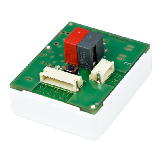
Fig. 1
KNX bus clamp
Programming button
Programming LED
Connect the bus cable (red/black clamp).
Use the 8-wire connection line to connect the outputs and the 4-wire line to connect the
binary inputs. The lines may be extended to up to 5 m.
Door operator control module KNX A3-B2 • Version: 17.12.2019 • Technical changes and errors reserved.
5
Outputs
(connector for 8-wire line)
Fig. 2
8-wire connection line for outputs:
blue
black
violet
black
yellow
black
white
black
Connection of the outputs independent from polarity.
Installation and start-up
Binary inputs
(connector for
4-wire line)
output 3
output 3
(not connected)
output 2
output 2
(not connected)
output 1
output 1