- ページ 5
計測機器 elsner elektronik 40102のPDF 技術仕様と設置手順をオンラインで閲覧またはダウンロードできます。elsner elektronik 40102 11 ページ。 Indoor sensor and ventilation control
•
Drafts from windows and doors
•
Draft from ducts which lead from other rooms or from the outside to the
junction box in which the sensor is mounted
•
Warming or cooling of the building structure on which the sensor is mounted,
e.g. due to sunlight, heating or cold water pipes
•
Connection lines and ducts which lead from warmer or colder areas to the
sensor
Measurement variations from such sources of interference must be corrected in the
basic settings menu in order to ensure the specified accuracy of the sensor.
2.3. Sensor connection and design
2.3.1. Housing
1
2
2.3.2. Connection board
1
Fig. 2
1
Socket for 4-wire connecting cable
(only with TH PF-U), see Fig. 3
2
Socket for 8-wire connecting cable, see Fig. 4
2
Ventilation Controls TH PF(-U)
Status: 19.04.2016 • Technical Changes and Errors excepted.
5
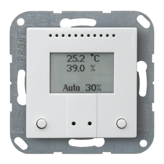
Fig. 1
1
Base plate
3
2
Catches
3
Openings for air circulation
4
CLOSE/- button
5
CLOSE/- LED (recessed)
4
6
OPEN/- LED (recessed)
5
7
OPEN/- button
8
Openings for air circulation
6
(LOWER)
7
8
Installation and start-up