- ページ 4
デジタルカメラ CBC HSW-H37のPDF 取扱説明書をオンラインで閲覧またはダウンロードできます。CBC HSW-H37 5 ページ。 Security height marker camera

1. UNPACKING
Unpack carefully. This equipment should be handled with care.
Check for the following items:
• Verify the unit model number.
• Verify that parts listed below have been included.
If an item appears to have been damaged in shipment, replace it properly in its carton and notify the shipper. If
any items are missing, notify your dealer or Sales Representative or Customer Service. The shipping carton is the
safest container in which the unit may be transported. Save it for possible future use.
Height Marker Camera
Hardware Kit
2 x Cable Ties
2 x Cable Tie Mounts
3 x Plastic Wall Anchor
3 x #8 cross recessed self-tapping screw, 1-1/2" length
1 x Barrel Plug Connector, 2.1mm pin, 36" length, stripped leads
1x Power Supply 120V to 12VDC 500mA
2. INSTALLATION
Tools required:
#2 Cross Recessed Screwdriver (Philips)
Level
Wire Splice and Crimper or Wire Nuts
Drill with 3/16" bit (Optional 1/8" bit)
Optional: Drill with ½" bit
Optional: De-burr tool
1. Choose desired location for camera installation. Verify mounting structure and
surface is capable of supporting the camera and no obstacle or interference is
present from existing installed devices or wiring.
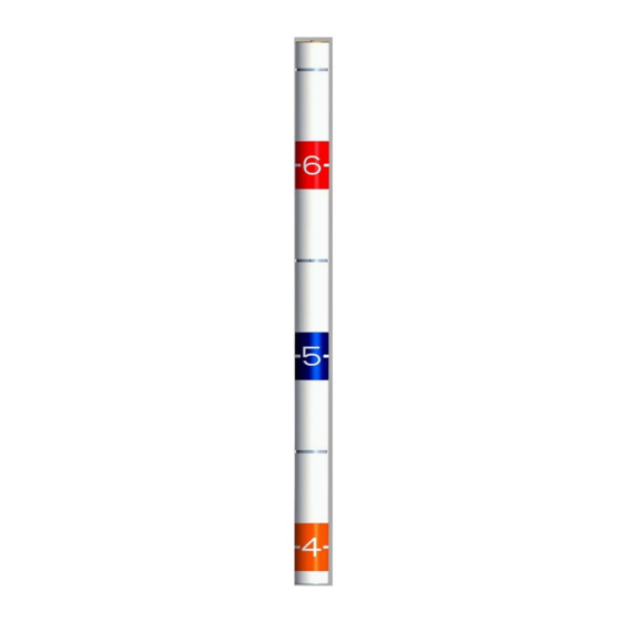
2. Measure a distance of 5 feet from the finished floor height and mark vertical
location.
3. Mark centerline of horizontal location.
4. For plastic anchors, drill a 3/16" hole at intersection of the vertical and horizontal
marks. If the anchors are not being used, drill a 1/8" hole in mounting surface.
5. Install plastic anchor and #8 screw. Do not tighten.
6. Remove cover from Height Marker Camera by removing screw from top cover, then
slide cover up and lift.
7. Place center mounting keyhole in base over installed #8 screw. Level and align
camera base and frame.
8. Mark top and bottom mounting locations.
If wiring connection is being made through the back of the camera base frame.
Mark wire ingress location.
9. Remove camera base frame and set aside.
10. Drill 3/16" hole at mounting location marks and install anchors.
If wiring connection is being made through the back of the camera base frame. Drill
wire ingress holes.
11. Place base over installed #8 screw, tighten screw, install and tighten top and
bottom mounting screws.
Confidential
Page 4
Slide cover up
and lift to open
Slide cover down
and in to close
