- ページ 4
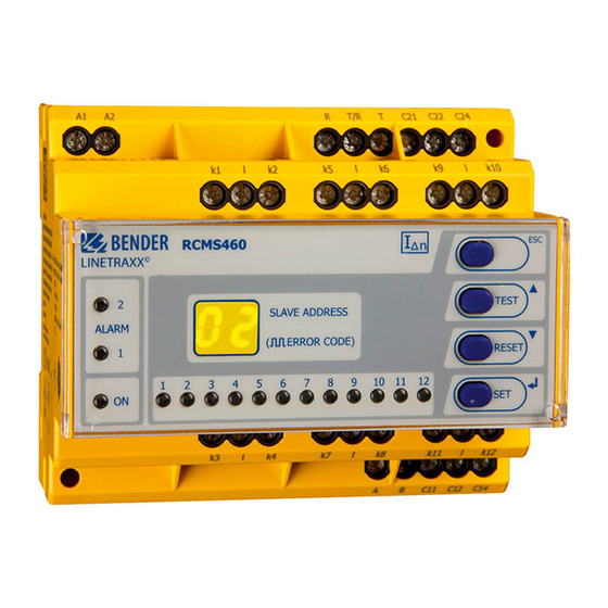
モニター Bender B94053007のPDF クイック・スタート・マニュアルをオンラインで閲覧またはダウンロードできます。Bender B94053007 8 ページ。 Multi-channel residual current monitors for earthed ac, dc and ac/dc systems (tn and tt) ac, pulsed dc and ac/dc sensitive

Anschlussbild RCMS4...
Beschreibung
Anschluss U
(s. Bestellangaben), Sicherung: Empf.: 6 A
S
Anschluss CT1...CT12, wahlweise Typ A oder Typ B pro Kanal.
Für Messstromwandler der Serie CTUB100 bzw. CTBS25 wird ein
24-V-DC-Netzgerät benötigt.
RCMS4...-D4/-L4: Kanäle K9...12 nur für Messstromwandler
Typ A
BMS-Bus (RS-485-Schnittstelle mit BMS-Protokoll)
Externe Reset-Taste (Schließer). Externe Reset-Tasten mehrerer
Geräte dürfen nicht miteinander verbunden werden.
Externe Test-Taste (Schließer). Externe Test-Tasten mehrerer
Geräte dürfen nicht miteinander verbunden werden.
Sammelalarmrelais K1: ALARM 1
Sammelmeldung für Hauptalarm, Vorwarnung, Gerätefehler.
Sammelalarmrelais K2: ALARM 2
Sammelmeldung für Hauptalarm, Vorwarnung, Gerätefehler.
Abschlusswiderstand des BMS-Busses (120 Ω) ein- oder aus-
schalten.
Messstromwandler
(Serie CTAC..., CTUB100, CTBS25, WR..., WS..., WF...)
Alarmrelais pro Kanal: jeweils ein Schließer pro Messkanal
(z. B. Schließerkontakte 11,14 für Kanal 1).
4
RCMS460-490_D00067_00_Q_XXDE / 03.2021
Element
A1, A2
Connection of U
Connection CT1...CT12, either type A or type B for each mea-
suring channel. When using measuring CTUB100 or CTBS25
k1, l ... k12, l
series, a 24 V DC power supply unit is required.
RCMS4...-D4/-L4: The channels k9...k12 require the
connection of type A measuring current transformers.
A, B
BMS bus (RS-485 interface with BMS protocol)
External reset button (N/O contact). The external reset but-
R, T/R
tons of several devices must not be connected to one another.
External test button (N/O contact). The external test buttons
T, T/R
of several devices must not be connected to one another.
Common alarm relay K1: Alarm 1, common message for main
C11, C12, C14
alarm, prewarning, device error.
Common alarm relay K2: Alarm 2, common message for main
C21, C22, C24
alarm, prewarning, device error.
Activate or deactivate the terminating resistor of the BMS
Ron/off
bus (120 Ω )
Measuring current transformers
CT
(CTAC..., CTUB100, CTBS25, WR..., WS..., WF... series)
11, 14 ...
Alarm relay per channel: One N/O contact per measuring
121, 124
channel (e.g. N/O contacts 11,14 for channel 1).
Wiring diagram RCMS4...
Description
(see ord. information), recomm.fuse: 6 A
S
