- ページ 4
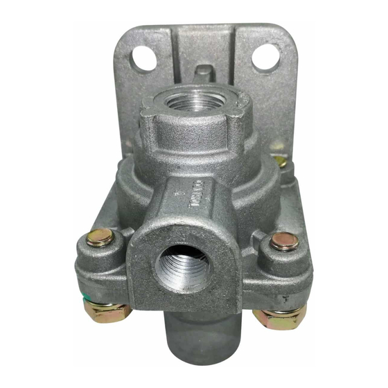
コントロールユニット BENDIX LQ-2 QUICK RELEASE VALVESのPDF マニュアルをオンラインで閲覧またはダウンロードできます。BENDIX LQ-2 QUICK RELEASE VALVES 4 ページ。 Limiting & quick release valve and control valve

CLEANING AND INSPECTION
Wash all metal parts in mineral spirits; wipe rubber parts dry.
Inspect all parts for signs of wear and/or deterioration.
Inspect springs for cracks, distortion or corrosion and inspect
all metal valve seats for nicks or scratches.
It is recommended that all rubber parts be replaced, and
that any part showing signs of wear or deterioration be
replaced.
ASSEMBLY
LIMITING AND QUICK RELEASE VALVE
1. Install inlet valve on stem (note: lubricating the valve with
silicone will aid installation).
2. Insert stem through pistons, position spring and valve
guide over stem and press exhaust valve boot on stem.
3. Lubricate body and cover bores, o-rings and o-ring grooves
with Dow Corning 55M pneumatic grease (Bendix piece
no. 291126).
4. Install o-rings on piston assembly.
4
BW1439 © 2004 Bendix Commercial Vehicle Systems LLC All rights reserved. 3/2004 Printed in U.S.A.
5. Install piston assembly in body. Be careful not to damage
o-rings.
6. Install sealing ring in body; install cover to body.
7. Install four (4) cap screws/lockwashers; torque to
approximately 100 inch pounds.
™
TW-1
CONTROL VALVE
Prior to assembly, lubricate body bores, plunger and o-rings
with Dow Corning 55-M pneumatic grease (Bendix piece
no. 291126).
1. Install inlet/exhaust valve and spring in body.
2. Install cap nut and sealing ring.
3. Install plunger o-ring, plunger spring and plunger into
body.
4. Position lever in body slot, line up lever hole and install
pin.
5. Test valves as outlined in "Operating and Leakage" test
section.
