- ページ 3
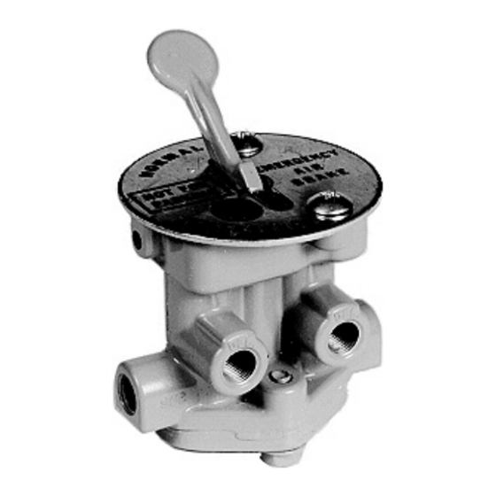
コントロールユニット BENDIX PE-4のPDF インストレーション・インストラクションをオンラインで閲覧またはダウンロードできます。BENDIX PE-4 4 ページ。 Control valves maintenance kit

REMOVAL
1. With the vehicle on a level surface, park the vehicle
by means other than the air brakes and drain all air
pressure from all reservoirs.
2. Identify all air lines and their connections to the valve
and disconnect.
3. Remove the two Phillips
plate to the valve and dash panel and remove the valve.
DISASSEMBLY
NOTE: Before beginning disassembly of the valve, mark
the relationship of the lever and cam to the body. The lever
must be placed back in the valve body in the same position
in order to ensure proper operation. DO NOT change the
lever position end for end. Most lever/cams have a locating
slot cut in them.
1. Remove the cap screws and lock washer and remove
the inlet plate. Note whether one or two inlet plate
o-rings (2) are used. *See note on page 1.
2. Remove and discard the o-ring (2), both springs (3) and
both inlet valves (4).
3. Remove the pin and lift the lever out of the body.
4. Remove both plungers and their return springs (5).
5. Remove the lever positioner and its spring, if the valve
is so equipped.
6. Remove the o-ring (6) from both plungers and discard
the o-rings.
ASSEMBLY
Prior to assembly, clean the lever and valve body in
mineral spirits and dry thoroughly. Lubricate o-rings and
o-ring bores with the lubricant (7) supplied with this kit.
1. Install both inlet valves (4) and inlet valve springs (3) in
the valve body.
2. Install the o-ring or o-rings (see NOTE* on page 1) in
the valve body.
head screws securing the dial
®
3. Install the inlet plate and secure with cap screws and
washer. Torque to 50-180 in-lbs.
4. Install the o-ring (6) on the plungers.
5. Install the plunger return springs (5) and install the
plungers in the valve body.
6. Install the lever positioner spring and lever positioner if
valve is so equipped.
7. Note the markings made on the lever/cam and valve
body during disassembly and position the lever in the
valve body.
8. Install the pin to secure the lever/cam.
OPERATING AND LEAKAGE CHECKS
Connect a 100 psi air source to the supply port(s) and
connect an air gauge to each delivery port. With the lever
in the number 1 position, as noted in Figure 3, apply a soap
solution to the exhaust openings in the valve body. No
leakage is permitted. Note which delivery gauge registers
pressure (if either do). Move the lever to position 2, if the
valve has this position, and wait 20 seconds before applying
a soap solution and checking the delivery port gauges.
Repeat this procedure for position 3.
INSTALLATION
1. Remount the valve in the dash panel using the two
Phillips head screws to secure the dial plate and valve.
2. Noting the air line identification made during removal,
reconnect the air lines to the proper ports.
3. Before moving the vehicle, build the air system pressure
and operate the valve to determine if it functions
properly in the system. If operation is incorrect, check
the lever/cam installation and the air line connections.
3
