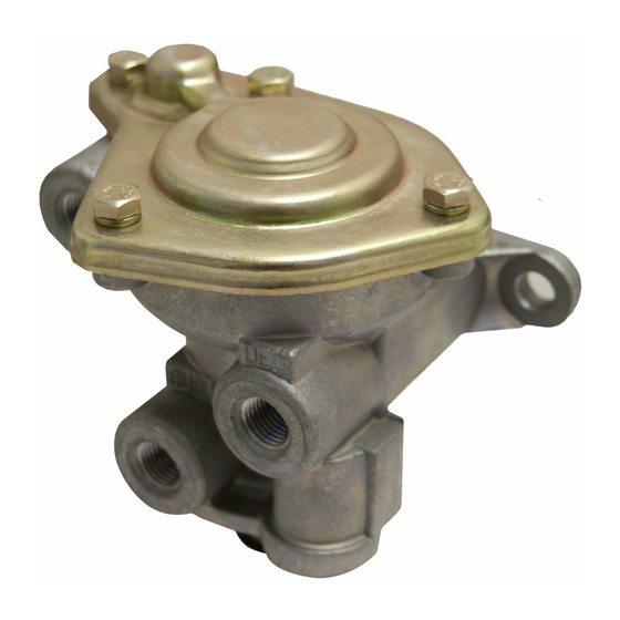
コントロールユニット BENDIX SR-1 SPRING BRAKE VALVEのPDF マニュアルをオンラインで閲覧またはダウンロードできます。BENDIX SR-1 SPRING BRAKE VALVE 8 ページ。 Spring brake valve

®
™
Bendix
SR-1
1/4 P.T.
RES. #1
1/4 P.T.
CONTROL
FIGURE 1 - EXTERIOR VIEW
DESCRIPTION:
The SR-1
™
spring brake valve is used in dual or "split" air
brake systems equipped with spring brake actuators. The
function of the SR-1
™
valve is to supply a specific, limited
hold-off pressure to the spring brakes, and in the event of
loss of No. 1 service air pressure, to modulate the spring
brakes through the use of the service brake valve.
The valve has four identified 1/4" N.P.T.F. ports and a
diaphragm protected exhaust port. Two 5/16" diameter holes
are provided in the integral mounting bracket of the valve
™
body. The SR-1
valve must be mounted with the exhaust
port down toward the road surface.
OPERATION - INITIAL AIR SYSTEM CHARGE
Upon initial charge, air from #1 & #2 service reservoirs flows
through the park control valve and enters the SR-1
supply port. Air entering the supply port flows past inlet and
exhaust valve B to the underside of piston B and out the
delivery port of the SR-1
connection at the spring brake actuator. Note that the springs
above piston B force it into contact with inlet and exhaust
valve B. In the position shown the exhaust is closed and the
inlet is open.
Spring Brake Valve
1/4 P.T.
DELIVERY
1/4 P.T.
SUPPLY
™
valve to the emergency air
PISTON SPRING
(14)
PISTON (15)
PISTON O-RINGS
(16)
VALVE (12)
VALVE SPRING (11)
VALVE STOP (10)
O-RING (9)
CAP NUT
(8)
FIGURE 2 - SECTIONAL VIEW
Air flowing from the No. 1 reservoir only enters the reservoir
port of the SR-1
system pressure builds. With No. 1 reservoir pressure below
approximately 55 P.S.I. the spring above piston A forces it
into contact with inlet and exhaust valve A causing the
exhaust to seal and the inlet to open.
With air system pressure above approximately 55 P.S.I. in
No. 1 & 2 service reservoirs, piston A has moved against
the force of the spring above it, allowing the inlet of valve A
to close and opening the hollow exhaust passage through
piston A.
OPERATION - AIR BRAKE SYSTEM FULLY
CHARGED
When air pressure beneath piston B is approximately 95*
P.S.I., piston B rises slightly, against the force of the springs
™
valve
above it, allowing the inlet of valve B to close. The exhaust
through valve B remains closed. The closing of the inlet
portion of valve B retains approximately 95* P.S.I. in the
hold- off cavity of the spring brake actuators while allowing
full air system pressure to build elsewhere.
*Note: Other spring brake hold-off pressures are supplied
according to the vehicle manufacturer's
specifications. 95 P.S.I. was chosen only for the
purpose of explanation.
PISTON
COVER (13)
SPRINGS (14)
INLET &
EXHAUST
DIAPHRAGM
VALVE (7)
(6)
™
valve. This air remains under piston A as
O-RING
(LARGE)
(18)
PISTON (17)
O-RING
(SMALL) (19)
BODY
CHECK
VALVE (4)
CHECK
VALVE SPRING (2)
PIPE PLUG
(1)
EXHAUST
COVER (5)
1
