- ページ 2
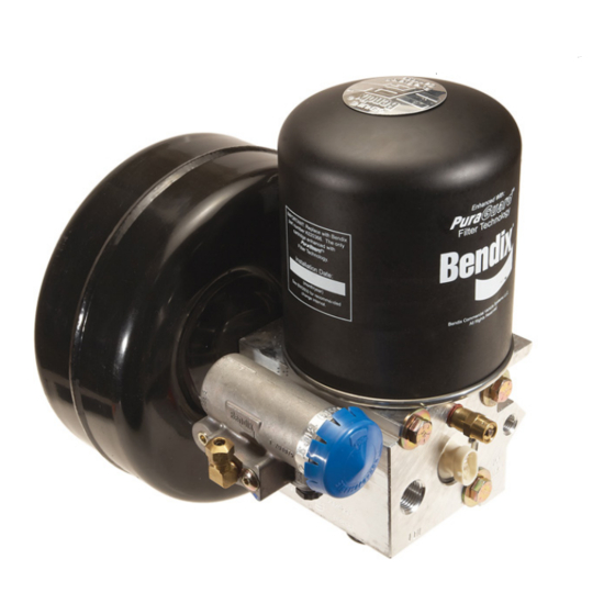
除湿機 BENDIX AD-IS -のPDF マニュアルをオンラインで閲覧またはダウンロードできます。BENDIX AD-IS - 17 ページ。 Air dryer and reservoir system
BENDIX AD-IS - にも: パンフレット (2 ページ), サービスデータ (15 ページ)

- 1. Air Dryer/Reservoir System Charge Cycle
- 2. Air Dryer/Reservoir System Purge Cycle
- 3. Charge Cycle
- 4. Purge Cycle
- 5. Preventive Maintenance
- 6. Operation & Leakage Tests
- 7. Pressure Protection Valve Locations
- 8. Testing
- 9. Braking System Protection & Inspection
- 10. Temporary Air Dryer/Reservoir System Bypass
- 11. Delivery Check Valve Cleaning Procedure
- 12. Cleaning and Inspection
- 13. Troubleshooting
DESICCANT
BED
DELIVERY
GOVERNOR
CHECK
VALVE
(OPEN)
UNLOADER
PORT
PURGE
CONTROL
CHANNEL
INLET
PORT
(IN)
TURBO CUT-
OFF VALVE
(OPEN)
PURGE
VALVE
(CLOSED)
®
FIGURE 2 - AD-IS
AIR DRYER AND RESERVOIR SYSTEM CHARGE CYCLE
The function of the pressure protection valves is to protect
each reservoir from a pressure loss in the other reservoir or
a pressure loss in an air accessory. Each of the pressure
protection valves in the AD-IS
may have different pressure settings, but these are factory
set and must not be changed or adjusted.
The air dryer and reservoir system consists of a "spin on"
desiccant cartridge secured to a base assembly. The base
assembly contains a delivery check valve assembly, safety
valve, heater and thermostat assembly, pressure protection
valves, threaded air connections and the purge valve
assembly.
2
SAFETY
SEE
VALVE
NOTE 1
PRIMARY
PORT
(PRI)
SECONDARY
PORT
(SEC)
ENGINE
TURBO
COMPRESSOR
PRIMARY
RESERVOIR
®
air dryer and reservoir system
OIL
SEPARATOR
PRESSURE PROTECTION
VALVES
A
B
C
AUXILIARY PORTS
(TO ACCESSORIES)
The removable purge valve assembly incorporates the purge
valve mechanism and a turbocharger cut-off feature that is
designed to prevent loss of engine "turbo" boost pressure
during the purge cycle of the AD-IS
system. For ease of maintenance, all replaceable
assemblies can be serviced without removal of the air dryer
and reservoir system from its mounting on the vehicle. Refer
to Preventive Maintenance section.
Note 1:
®
The AD-IS
air dryer and reservoir system
purge piston has a purge control channel
drain. This allows any condensation in this
area to flow past a diaphragm in the top of the
purge piston and out through a channel in
the middle of the central bolt of the purge
assembly to be drained. During the purge
cycle this drain is closed.
PURGE
PURGE
ORIFICE
RESERVOIR
D
PURGE
RESERVOIR
DRAIN VALVE
SECONDARY
RESERVOIR
DIAGRAM SHOWS PRESSURE
PROTECTION VALVES A & B OPEN,
C & D CLOSED.
®
air dryer and reservoir
