- ページ 2
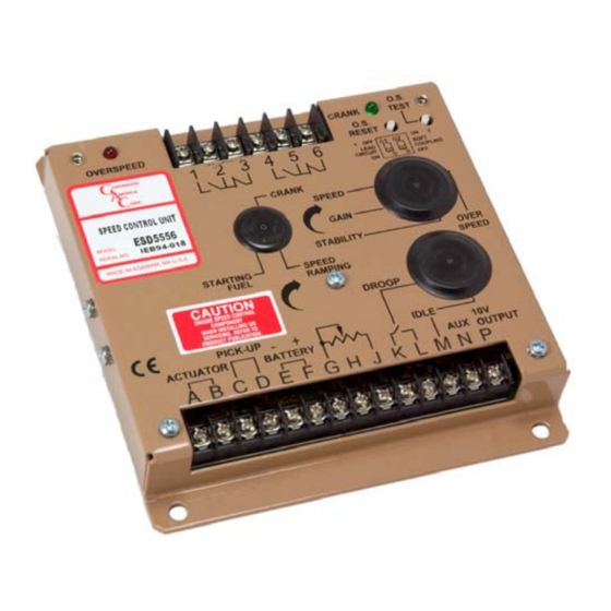
コントロールユニット GAC ESD-5556のPDF 技術情報をオンラインで閲覧またはダウンロードできます。GAC ESD-5556 12 ページ。 Speed control unit

WIRING
Basic electrical connections are illustrated in Diagram 2 (for the ESD-5550, ESD-5555 and the
ESD-5570) and Diagram 3 (for the the ESD-5556 only). Actuator and battery connections to
Terminals A, B, E, and F should be #16 AWG (1.3 mm
wire size to minimize voltage drops. The battery positive (+) input, Terminal F, should be fused for
15 amps as illustrated.
Magnetic speed sensor wires connected to Terminals C and D MUST BE TWISTED AND/OR
SHIELDED for their entire length. The speed sensor cable shield should ideally be connected as
shown in Diagram 2 or 3. The shield should be insulated to insure no other part of the shield
comes in contact with engine ground, otherwise stray speed signals may be introduced into the
speed control unit. With the engine stopped, adjust the gap between the magnetic speed sensor
and the ring gear teeth. The gap should not be any smaller than 0.020 in. (0.45 mm). Usually,
backing out the speed sensor 3/4 turn after touching the ring gear teeth will achieve a satisfactory
air gap. The magnetic speed sensor voltage should be at least 1 VAC RMS during cranking.
ADJUSTMENTS
Before Starting Engine
Before starting the engine, check and/or adjust the POTs/switches to the following settings. See
Table 2 for the factory presets.
Adjustment/Switch
SPEED
GAIN
STABILITY
DROOP
IDLE
STARTING FUEL RAMP
SPEED RAMP
OVERSPEED
CRANK TERMINATION
SW1 Lead Circuit
SW2 Soft Coupling
Start Engine
The speed control unit governed speed setting is factory set at approximately engine idle speed.
(1000 Hz., speed sensor signal) Crank the engine with DC power applied to the governor
system. The governor system should control the engine at a low idle speed. If the engine is
unstable after starting, turn the GAIN and STABILITY adjustments CCW until the engine is
stable.
Technical Information
Potentiometer/Switch
25° turn
270° turn
270° turn
270° turn
270° turn
270° turn
270° turn
25° turn
25° turn
switch
switch
2
) or larger. Long cables require an increased
Setting
1470 Hz 1/- 50 Hz w/min trim
50%
50%
0% (CCW)
1075± 75 Hz
100% (CW) Maximum Fuel
0% (CCW) Fastest
100% (CW) Highest
0% (CCW) Lowest
ON
OFF
Applicable Units
all
all
all
all
all
all
all
all
ESD-5556 only
all
all
