- ページ 10
ツール Gage Bilt GB713のPDF オリジナル取扱説明書をオンラインで閲覧またはダウンロードできます。Gage Bilt GB713 18 ページ。
Gage Bilt GB713 にも: インストレーション・マニュアル (14 ページ), オリジナル取扱説明書 (20 ページ)
WARNING:
WARNING:
Do not cycle tool without air bleeder assy (704153), or the screw and stat-o-seal, installed in tool head. Severe personal injury could result.
Do not cycle tool without air bleeder assy (704153), or the screw and stat-o-seal, installed in tool head. Severe personal injury could result.
WARNING:
WARNING:
Use CAUTION when removing screws, air bleeder assy (704153) and fill bottle (745263). Hydraulic oil may be under pressure.
Use CAUTION when removing screws, air bleeder assy (704153) and fill bottle (745263). Hydraulic oil may be under pressure.
CAUTION:
CAUTION:
Before filling handle assy (744129), air piston assy (744121) should be all the way down.
Before filling handle assy (704132), air piston assy (704121) should be all the way down.
CAUTION:
CAUTION:
When forcing piston rod assy (704138) downward, with head cylinder assy (751109) removed, hydraulic oil will eject forcibly
When forcing piston rod assy (744136) downward, with head cylinder assy (713121) removed, hydraulic oil will eject forcibly
from handle assy (704132).
from handle assy (744129).
CAUTION:
CAUTION:
When bleeding tool, ensure tubing is free from kinks or other obstructions.
When bleeding tool, ensure tubing is free from kinks or other obstructions.
Note:
Note:
Air Bleeder Assy (704153) is required.
Air Bleeder Assy (704153) is required.
To replace a small amount of oil follow BLEEDING steps 4-6.
To replace a small amount of oil follow BLEEDING steps 4-6.
1. Remove four button head cap screws (402479) and head cylinder assy (713121) from handle assy (744129). Slowly push piston
(713211) completely forward.
2. Fill handle assy (744129) and the oil passage on top of handle assy (744129) with automatic transmission oil, Dexron III or
equivalent. When looking at the top of the handle assy (744129), the oil passage is the hole that is counterbored for o'ring (S832).
3. Replace head cylinder assy (713121) with care, ensuring gasket (704129) and o'ring (S832) are properly installed. Torque button
head cap screws (402479) uniformly to 40 inch lbs. to prevent leakage around gasket (704129).
4. Remove button head cap screw (402482) and stat-o-seal (S572) from head cylinder assy (713121). Install air bleeder assy (704153)
and connect tool to air line. Cycle ten times to fully circulate oil through hydraulic system.
5.
DISCONNECT AIR FROM
(S572) on head cylinder assy (713121). Torque 35-40 inch lbs.
6. Reconnect air and cycle tool 10 more times. Check tool stroke. We recommend using dial calipers. With the air actuator assy
(704130) released check dimension (A). Holding air actuator assy (704130) in, check dimension (B). Subtract dimension (A)
from dimension (B). If stroke doesn't check .760" (19.3 mm) min. (See figures below) repeat steps 4 thru 6.
Bleeder hole on head cylinder (713121)
Button head cap screw (402482) & stat-o-
seal (S572)
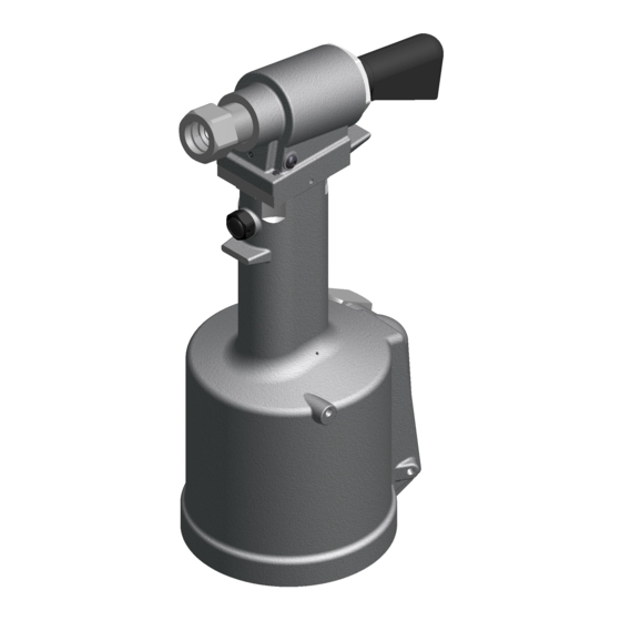
GB713
FILLING AND BLEEDING PROCEDURE:
FILLING AND BLEEDING PROCEDURE:
TOOL. Remove air bleeder assy (704153) and install button head cap screw (402482) and stat-o-seal
Image may not reflect actual tool.
Air Bleeder Assy (704153)
10
7/11 REV 6/16