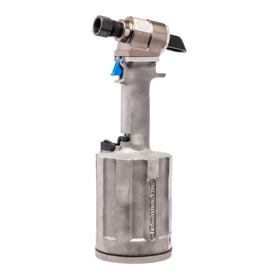
HEAD
Remove nose assembly from tool before attempting disassembly of head assembly.
Remove deflector (756120) and end cap (756116). Push against threaded end of piston assembly (756211) to slide it out
of head cylinder (756300). Be careful not to damage threads or cause burrs on polished piston rod ass'y surface.
WARNING:
DISPOSE OF HYDRAULIC FLUID IN ACCORDANCE WITH ALL ENVIRONMENTAL LAWS AND REGULATIONS
APPLICABLE TO YOUR AREA.
The re-assembly sequence is the opposite of disassembly. (See Filling and Bleeding instructions.) Apply Loctite® #242
and torque the four button-head cap screws (402479) uniformly to 35-40 inch lbs. to prevent leakage around the gasket
(756148).
402482 - BUTTON HD. SCREW
402482 - BUTTON HD. SCREW
401092 - BACK-UP RING
480101 - PINTAIL TUBE
753101 - NOSE FITTING
480124 - NUT
480125
RETAINING NUT STOP
HANDLE
To inspect air cylinder bore, remove bottom plate (756144), spring (50607), muffler (756145), o'ring (400777), gasket
(756149), retaining ring (A-1086) and base cover (756124). Any further disassembly will require removal of the head
cylinder (756300) first. For complete disassembly, start by removing bottom plate (756144), muffler (756145), o'ring
(400777), gasket (756149), retaining ring (A-1086) and base cover (756124). Next, holding tool upright, remove four
button-head cap screws (402479). Lift head cylinder (756300), gasket (756148) and gland (756126) from handle (756229).
Empty all hydraulic fluid into an approved container and dispose of in accordance with all environmental laws and
regulations applicable in your area. Place tee wrench down into top of power cylinder into hex on piston rod ass'y
(756134). While holding tee wrench, put a 9/16 socket wrench on flexlock nut (A-1089) and loosen piston rod cap "not
shown" from piston rod. Using vice grips, grab flexlock nut (A-1089) and remove air piston ass'y (756121) from bottom
of handle (756229). After removal of air piston ass'y (756121), use packing plug wrench (756151) and remove packing
plug (756218). Stand tool upright and carefully push on top of power cylinder (756227) to eject from bottom of handle
not letting it drop and nick large cylinder bore handle. Remove pston rod cap from inside of power cylinder (756227).
To reassemble the handle (756229), reverse the above procedure, being certain that all o'rings are properly lubricated.
After installing the power cylinder (756227), install the packing plug (756218) and torque to 45 foot lbs. Push piston rod
ass'y (756134) thru the packing plug (756218) with the air piston ass'y (756121) attached. Install piston rod cap back into
the power cylinder (756227) and tighten securely to the piston rod using tee wrench and 9/16 socket wrench. Re-install
the spring (50607), muffler (756145), o'ring (400777), gasket (756149) and base cover (756124), retaining ring (A-1086)
and bottom plate (756144). With piston rod ass'y (756134) in the down position, fill oil passages on top of handle
(756229) with automatic transmission fluid.
S/N: 1226 AND ABOVE
PLEASE CONTACT GAGE BILT FOR ALL OTHER SERIAL NUMBERS.
A-1155
STAT-O-SEAL
(2 REQ'D)
A-1103 - O'RING
403775 - O'RING
401091 - BACK-UP RING
756211 - PISTON ASSEMBLY
401119 - BACK-UP RING
403815 - O'RING
401119 - BACK-UP RING
756300 - HEAD CYLINDER
405790 - O'RING
405530 - O'RING
401082 - BACK-UP RING
756126 - GLAND
401084 - BACK-UP RING
S829 - O'RING
9
756120
DEFLECTOR
A-1084 - O'RING
401117 - BACK-UP RING
A-1082 - O'RING
756116 - END CAP
REV. 3/14