- ページ 4
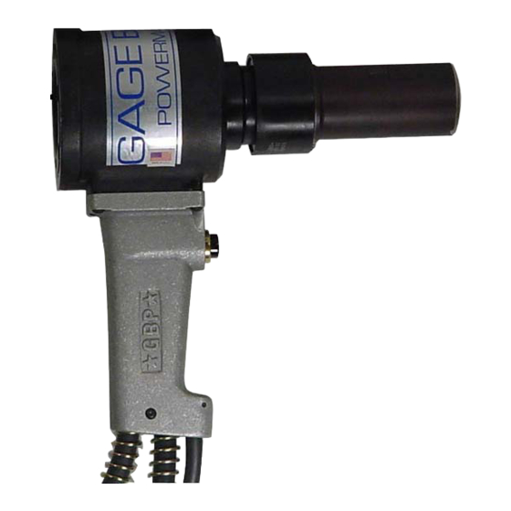
リベット工具 Gage Bilt GB585のPDF インストールをオンラインで閲覧またはダウンロードできます。Gage Bilt GB585 11 ページ。 Installation tool
Gage Bilt GB585 にも: オリジナル取扱説明書 (20 ページ)
PRINCIPLE OF OPERATION
When the tool is connected to a powerunit, operation is controlled by the switch/actuator in the handle assy. When the switch/
actuator is depressed, a directional valve in the powerunit directs oil to the front side of the piston forcing it and the nose assembly
collet rearward. This action causes the jaws to clamp onto the fastener pintail and pull the sheets together. The anvil is forced for-
ward, swaging the collar into locking grooves of the fastener. Further force breaks the pintail off, approximately flush with the collar.
When the switch/actuator is released the directional valve reverses oil flow to the back of the piston assy and pushes the nose as-
sembly off of the swaged fastener. The pintail ejector hydraulically pushes the spent pintail out of the nose assembly.
HOW TO USE THE GB585/GB585A
WARNING:
Operator
WARNING:
It is required that eye protection and hearing protection be worn during operation.
WARNING:
Do not pull rivet in the air. Personal injury from fastener ejecting may occur.
CAUTION:
Do not use beyond the design intent.
#1. Set power supply to the recommended pressure, 5,700 psi (393.0 bar) for the pull and 2,400 psi (165.5 bar) for the return.
#2. Connect hydraulic hose assy's (505034) to supply and control cord assy (585034) to the power supply for GB585.
Connect hydraulic hose assy's (505034) and air quick disconnect (208127) to supply for GB585A.
WARNING:
Ensure air hose is securely connected to avoid possible hose whipping.
#3. To ensure piston is in the full forward position, Cycle tool.
#4. Disconnect hydraulic hose assy's (505034) and control cord assy (585034) from the power supply for GB585.
Disconnect hydraulic hose assy's (505034) and air quick disconnect (208127) from the supply for GB585A.
#5. Select proper Nose Assembly
#6. Screw collet assembly onto piston until top of collet flat lines up with top of tool.
#7. If Collet Lock is not in Piston groove, continue to turn 1/4 turn, or less until lock engages groove.
#8. Tighten Set Screw.
#9. Slide Anvil over assembled Collet. Install split ring, sleeve and retaining ring (furnished with tool).
(See proper data sheet for further instructions.)
#10. Re-connect hydraulic hose assy's (505034) to supply and control cord assy (585034) to the power supply for GB585.
Re-connect hydraulic hose assy's (505034) and air quick disconnect (208127) to the supply for GB585A.
Note: GBP7624B NOSE ASSEMBLY ATTACHMENT video may be viewed as a reference, located on our website, at :
www.gagebilt.com/videos.htm
WARNING:
Be sure there is adequate clearance for tool and operator's hands before proceeding. Keep fingers clear of any
moving parts. Keep fingers clear from fasteners and installed materials. Severe personal injury may result.
MUST
read and understand all warnings and cautions.
4
REV. 1/15