- ページ 4
リベット工具 Gage Bilt GB704のPDF インストレーション・マニュアルをオンラインで閲覧またはダウンロードできます。Gage Bilt GB704 13 ページ。 Installation tool
Gage Bilt GB704 にも: マニュアル (14 ページ), オリジナル取扱説明書 (20 ページ)
PRINCIPLE OF OPERATION
When the actuator lever assy is depressed, the pressurized air inside of the tool is released allowing spring
pressure to move the valve spool assy causing the air to be redirected. The air is directed to the top of the air
piston assy, moving it in a downward direction. The air below the air piston assy is then directed through the
valve sleeve and exhausted out of the bottom of the tool. Simultaneously, the piston rod assy connected to
the air piston assy is also moving down, forcing hydraulic oil up and into the front side of the head cylinder
assy, causing the piston to move to the rear of the head cylinder assy. The internal components of the
attached nose assembly are also moving with the piston to start the fastener installation. When the fastener
installation is completed, the actuator lever assy is released. Air pressure is then built up inside of the handle
causing the valve spool assy to return to its original position and reversing the sequence directing air
pressure to the rear of the head cylinder assy, causing the piston to move to the forward position.
CYLINDER
HEAD
OIL
PRESSURE
AIR
PRESSURE
AIR
PISTON
GB704 S/N: 3213 AND ABOVE
PLEASE CONTACT GAGE BILT FOR ALL OTHER SERIAL NUMBERS.
HEAD
PISTON
PISTON
ROD
AIR
PRESSURE
VALVE
SPOOL
EXHAUST
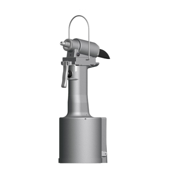
Image may not reflect actual tool.
AIR
PRESSURE
AIR
PISTON
AIR
PRESSURE
4
AIR
PRESSURE
AIR
PRESSURE
PRESSURE
6/11 Rev. 9/14
AIR