- ページ 6
水ポンプ Hi-Force AHP1142 SeriesのPDF 取扱説明書をオンラインで閲覧またはダウンロードできます。Hi-Force AHP1142 Series 8 ページ。 Air driven hydraulic pumps
Hi-Force AHP1142 Series にも: 取扱説明書 (8 ページ)
INSTRUCTION MANUAL – AIR DRIVEN HYDRAULIC PUMPS:
Model Series: AHP1120, AHP1120R, AHP1121, AHP1121R, AHP1122, AHP1122R, AHP1141, AHP1142,
HAP21011, HAP21012, HAP21014, HAP21016, HAP21021, HAP21022, HAP21024, HAP21026, HAP21031,
HAP21032, HAP21034, HAP21036, HAP21041, HAP21042, HAP21044, HAP21046,
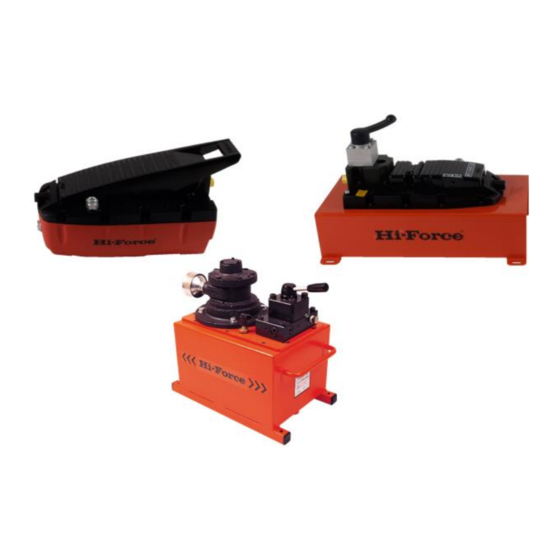
8.0 Description HAP series of Air Driven Pumps
Hi-Force HAP series pumps are designed to
operate high pressure hydraulic cylinders and
tools with a maximum working pressure of 700
bar. These instructions cover all HAP2-3 series
models. Refer to nameplate on pump for
model identification.
Common models and uses are given below:
MODEL
HYDRAULIC CONNECTIONS
HAP21011
No control valve fitted.
HAP21012
Pump
(P)
HAP21014
connections
HAP21016
double
controlled by remote mounted
valves.
HAP21021
2 way valve for operating single
HAP21022
acting
cylinders
HAP21024
requiring advance and retract
HAP21026
but
no
"hold"
example crimpers and cutters.
HAP21031
3 way valve for operating single
HAP21032
acting
HAP21034
advance, retract and central
HAP21036
load hold position. For example
simple lifting operations
HAP21041
4 way valve for operating double
HAP21042
acting
HAP31044
advance, retract and central
HAP21046
load hold position. For example
lifting and positioning requiring
more control.
9.0 Safety:
FAILURE
TO
OBSERVE
WARNINGS COULD RESULT IN SERIOUS BODILY
INJURY.
Ensure that all equipment connected
●
to the pump is in good condition and is
all rated for 700 bar operating pressure.
Always stand the pump on a stable
●
level surface during operation.
Never invert the pump or lay it on its
●
side either in use, transport or in
storage.
Inspect hoses regularly for damage
●
and wear. Do not use hoses that are
frayed, abraded or leaking.
Never move the pump by pulling the
●
hoses.
Do not work with hoses sharply bent or
●
kinked.
Do
not
handle
●
pressurised.
Oil
Hi-Force Limited – Prospect Way – Daventry – Northants NN11 8PL – United Kingdom
Tel: +44(0) 1327 301000: Fax: +44(0) 1327 706555: Website: www.hi-force.com
and
tank
(T)
for
single
and
acting
cylinders
and
tools
function.
For
cylinders
requiring
cylinders
requiring
THE
FOLLOWING
hoses
that
are
escaping
under
pressure
can
causing serious injury. If oil is injected
unde
the
skin
immediately.
Never pressurise uncoupled couplers.
●
Always
use
eye,
●
protective equipment when using this
pump and associated equipment
10.0 Identification of Components.
Refer to diagrams on following pages.
1.
Oil reservoir
2.
Hydraulic Oil level gauge
3.
Oil filler breather cap
4.
Motor
5.
Silencer
6.
Adjustable pressure relief valve
7.
Hydraulic directional control valve – if
fitted (type will vary)
8.
Hydraulic service connections
9.
Hydraulic oil drain plug
10. Roll frame (optional)
11. Motor air inlet.
penetrate
the
skin
see
a
doctor
ear
and
hand