- ページ 2
水ポンプ Hi-Force AHP36のPDF 取扱説明書をオンラインで閲覧またはダウンロードできます。Hi-Force AHP36 9 ページ。 Air driven hydrotest pumps
INSTRUCTION MANUAL – AIR DRIVEN HYDROTEST PUMPS:
Model Series: AHP10.AHP26, AHP36, AHP58, AHP107, AHP187, AHP275, AHP425,
AHP2-036, AHP2-060, AHP2-097, AHP2-144, AHP2-237, AHP3-040, AHP3-060, AHP3-100, ATDP63 ATDP125,
Once the above instructions have been
completed the Power Pack is ready for use and
the following operating procedure can be
followed:-
1.
Open the Air Stop Valve (2) (turn
clockwise) SEE FIGURE 1.
2.
Turn the Air Pressure Regulator (1)
slowly clockwise until the pump begins
to reciprocate. The pump should start
on 10 to 15 PSI of air under normal
conditions.
3.
Turn the Air Pressure Regulator (1)
clockwise further until 25 to 30 PSI is
reached on the Air Pressure Gauge (4),
and then allow the pump to run until all
air has been purged from the circuit.
Please note that when pressure testing
large vessels and pipes, care should be
taken to bleed off any air within the
object being tested.
4.
Turn the Air Pressure Regulator (1) anti-
clockwise until zero pressure is reached
on the Air Pressure Gauge (4).
5.
Close the Pressure Let-Down Valve (3)
(Turn clockwise).
6.
Close any further "Air Vent" valves,
external to the Power Pack once all air
has been purged from the total system.
7.
Turn the Air Pressure Regulator (1) slowly
clockwise until the desired hydraulic
pressure is reached on the High Pressure
Gauge (5)
Note
If the object being tested is large it will take a
while before the pressure builds up in the system
and registers on the high pressure gauge. Care
should be taken not to set the air driving pressure
too high whilst being unattended as this may
lead to the object under test being over
pressurised.
The air drive pressure can be pre-set if desired by
closing off the air stop valve prior to use and
winding the air pressure regulating valve
clockwise until the required air pressure is
registered on the air pressure gauge.
The air pressure should ideally be set slightly
below that desired so that it can be raised to the
correct amount once the output pressure has
built up and the pump has stalled out.
The pump can then be started and stopped by
using the air stop valve only if preferred.
Once set the pump will maintain the set pressure
indefinitely and make up any fluid losses within
the hydraulic system automatically.
To let down pressure
1.
Close off the Air Stop Valve (2) (Turn
anti-clockwise).
Hi-Force Limited – Prospect Way – Daventry – Northants NN11 8PL – United Kingdom
Tel: +44(0) 1327 301000: Fax: +44(0) 1327 706555: Website: www.hi-force.com
ATDP216,
2.
Turn the Air Pressure Regulator (1) anti-
clockwise until the Air Pressure Gauge
(4) is reading zero pressure.
3.
Open slowly the Pressure Let-Down
Valve (3) (Turn anti-clockwise) until the
high-pressure gauge reads zero.
4.
Disconnect the hydraulic hose from the
high-pressure outlet connection.
5.
Disconnect the air supply from the "Air
Supply Connection".
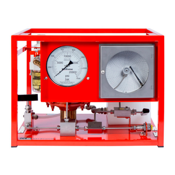
Figure 1
AHP2 SERIES – Hydrotest Pumps:
1.0 General Description:
The Hi-Force AHP2 range of Hydrotest pumps
are supplied from a range of 5 models with
output pressures ranging from 17 bar(246psi) to
1634bar (23700psi) and are suitable for use with
various fluids including water.
2.0 Before operating your Hi-Force Hydraulic
Power Pack please ensure that the following
instructions are carried out.
1.
Check that there is sufficient fluid in the
reservoir. If not, top up with mains
water or suitable hydraulic oil.
2.
Check that the "Pressure Let-Down
Valve" is in the open position (Turn anti-
clockwise).