- ページ 7
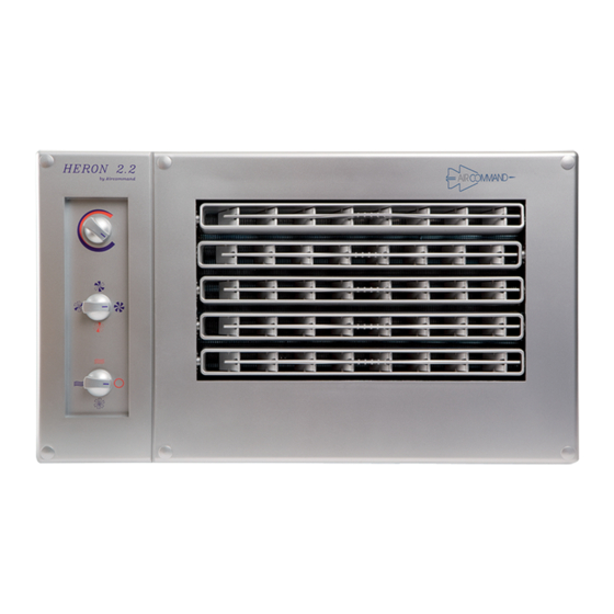
エアコン Aircommand HERON 2.2のPDF 取付説明書をオンラインで閲覧またはダウンロードできます。Aircommand HERON 2.2 10 ページ。
Aircommand HERON 2.2 にも: オーナーズマニュアル (17 ページ)

INSTALL BITUMINOUS TAPE AROUND 9.5 FLARE NUT AT THE A/H.
From the Installation kit provided, take the length of bituminous tape and wrap it around the
and joining the foam rubber insulation already on the pipe. The purpose of this is to avoid formation of
condensate, which may drip into the cupboard.
FITTING OF THE AIRHANDLER FACIA
With Leak testing of the A/H flare nuts completed and
bitumen tape installed, the Facia may now be fitted.
1. Feed the service lead into the cupboard, and plug into
the GPO, but leave turned off.
2. Plug in the Con/Set control cable to the back of the
switch box (6 pin plug) & clamp it with cable clamp
provided. Also plug in the A/H cable (9 pin). See
fig.14.
3. Now push the Facia fully into the cupboard front
panel. Check alignment, and using the c/s chipboard
screws supplied, screw the Facia at each corner. Use
the white plastic buttons provided to cover the screw
heads.
4. Check that the air direction vanes are free to rotate.
5. Turn on the power to unit.
6. Fit the 2 return air filters by pushing them into their
frames.
TEST TO BE CARRIED OUT BY INSTALLER PRIOR TO DELIVERY
COOLING: (ref fig.16)
NB. The unit will not run on cooling if the inside temp. is much
below 18°C.
1. Turn fan speed selector to
2. Turn mode selector to
3. Adjust the thermostat counter clockwise until the condenser
set is heard to start.
Ensure that cold air is being discharged, and there are no pipe
rattles etc. After about 15 minutes of running, and providing the
inside temp. is above 20°C, then the discharge air should be
12°C or cooler than the return air.
HEATING: (ref fig.16)
NB. The unit will not heat if inside temp. is much above 28°C.
1. Turn fan speed selector to
2. Turn mode selector to
3. Adjust the thermostat to max. clockwise position.
There will be approximately 30 seconds delay before heating
is apparent.
4. After about 15 mins. the discharge air will be approx. 25°C
more than the return air.
(Hi Speed Cooling)
(Cooling)
(Heating Speed)
(Heating)
7
Pluges must be
firmly pushed in
Cable clamp
Figure 14
Medium
cooling
Low cooling
speed
Heating speed
Heating
Cooling
3
/
flare nut
8
Final condensate connection can
be made reaching up through
return grilles. Also, wiring cables
may be tidies up and tied.
Figure 15
THERMOSTAT
FAN SPEED
SELECTOR
High speed
cooling
MODE
SELECTOR
Off
Fan only
(Ventilation)
Figure 16
