- ページ 3
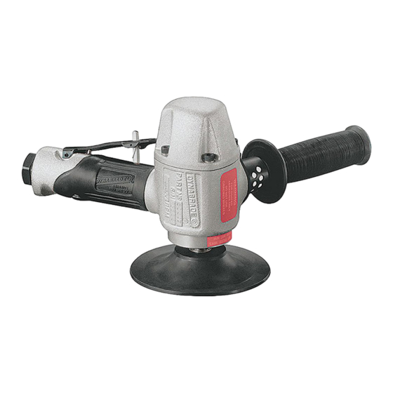
サンダー Dynabrade 50307のPDF マニュアルをオンラインで閲覧またはダウンロードできます。Dynabrade 50307 4 ページ。 4-1/2"– 5" vertical disc sander

• Hard density.
50275 – 5" Back-up Pad Assembly, 12,500 RPM max.
• Includes 50273 Flange Nut.
• Accepts abrasive discs with 7/8" center hole.
Disassembly/ ssembly Instructions — 4-1/2" – 5" Vertical Disc Sander
Important: Manufactures warranty is void if tool is disassembled before warranty expires.
Notice: All of the special repair tooling referred to in these instructions can be ordered from Dynabrade. Please refer to this parts page for the
Motor Disassembly:
proper part identification.
1. Shut the air supply to the tool and disconnect the tool from the air supply hose.
2. Remove the 50273 Flange, the abrasive and the 50275 Backing Pad.
3. Use a 5mm hex key to remove the 07190 Screws (4), 07191 Washers (4), 07129 Gasket and the 07161 Governor Cover from the 07126 Housing.
4. Pull the air motor out of the 07126 Housing.
5. Hold the 07135 Rotor Nut stationary and remove the governor assembly by turning it clockwise. (Left Hand Threads)
6. Fasten the 96346 Bearing Separator (2") around the portion of the 07118 Cylinder that is closest to the 07114 Rear Bearing Plate.
7. Position the motor assembly with the separator in the 96232 Arbor Press (#2) so that the threaded spindle of the 07104 Rotor is pointing down.
8. Use a 3/16" dia. flat end drive punch as a press tool along with the arbor press to push the rotor out of the 01007 Bearing.
9. Use the 96214 Bearing Removal Tool to remove the 01007 Bearing from the 07114 Bearing Plate.
10. Hold the vane slot portion of the 07104 Rotor in a vise with aluminum or bronze jaws, and remove the 07135 Rotor Nut by turning it counterclockwise.
11
Remove the 07120 Bearing Plate, 02552 Bearing and the 01277 Shims from the rotor.
Motor Disassembly Complete.
Valve Disassembly:
1. Remove the 07147 Plug by turning it counterclockwise.
2. Remove the 07146 Packing, the 07145 Spring, and the 07168 Valve Stem Assembly.
3. Remove the 01017 Pin and the 01089 Safety Throttle Lever.
Valve Disassembly Complete.
Muffler Disassembly:
1. Use a 5 mm hex key to remove the 50511 Screws (2), 01791 Washers (2), 07149 Clamp and the 01797 Exhaust Cover.
2. Remove the 01798 Felt Silencer and the 96304 Gasket.
Important: Clean and inspect all parts before assembling.
Muffler Disassembly Complete.
Muffler Assembly:
1. Install the 96304 Gasket onto the 07162 Housing.
2. Install the 01798 Felt Silencer into the 01797 Exhaust Cover and attach these to the 07162 Housing with the 07149 Clamp, 50511 Screws (2), and
the 01791 Washers (2).
Valve Assembly:
Muffler Assembly Complete.
1. Install the 07146 Packing onto the 07147 Plug.
2. Insert the 07145 Spring into the 07168 Valve Stem Assembly and install these into the 07141 Valve Body.
3. Secure the valve components in place with th 07147 Plug. (Torque to 17 N•m/150 in.- lbs.)
4. Install the 01089 Safety throttle Lever securing it in place with the 01017 Pin.
Valve Assembly Complete.
Mounting
rrangement
3
50272 – 5" Pad
50273 Flange Nut
