コントロールユニット Hi-Par HP600E ControlのPDF ユーザーマニュアルをオンラインで閲覧またはダウンロードできます。Hi-Par HP600E Control 2 ページ。 Controllable ballast
Installation Directions
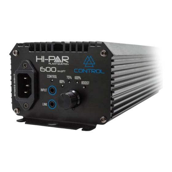
2. Power Cord
3. Magnet Ring
4. Power Input
1. Digital Ballast
8. Connect
7. Dimming Knob
Link Cable
STATUS
LED
Output lock down
1 Flash
Output errors
2 Flash
Low input voltage
3 Flash
Over temperature
4 Flash
High input
5 Flash
Note: When the controller is connected the CONTROL indicator LED ashes 2 times every 2
seconds - indicating controller is functioning correctly. However, if the Connect Link Cable is
removed during operation the ballast will shut down after 3 minutes. When operating
ballast without a HI-PAR Control Station the CONTROL indicator LED will be o . Turn power
o and on to reset the ballast when either connecting or disconnecting the Control Station.
MAINS POWER
MIN
MAX
BOOST
669
711
100%
615
657
75%
456
498
60%
361
402
E40 and DE
lamp compatible
5. OUTPUT to
HPS or MH lamp
6. Rubber Feet
BOX CONTENT:
1 x 600w Digital Ballast
1 x Power Cord
1 x Connect Link Cable
4 x Rubber Feet
1 x User Manual
LAMP POWER
MIN
MAX
BOOST
639
681
100%
579
621
75%
429
471
60%
339
381
USER MANUAL
HP600E Control for HPS and MH lamps
Data is based on operation of a standard HPS/MH lamp.
Supply power is based on typical commercial 240V,50/60Hz.
Performance
Model
Max Input
THD
Model
Voltage
Power
(V)
(W)
HP600E
240V
711
<10%
Control
Maximum
Power
Working
Ignitor
Current
Factor
Voltage
Voltage
(A)
(COSθ)
(V)
(kV)
3.0
.99
216-264
4.0