- ページ 4
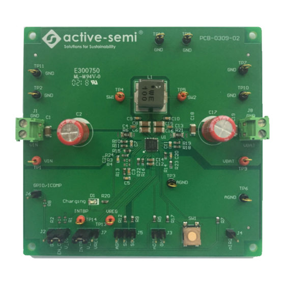
マザーボード Active-semi ACT2861EVK1-201のPDF ユーザーマニュアルをオンラインで閲覧またはダウンロードできます。Active-semi ACT2861EVK1-201 20 ページ。

Recommended Operating Conditions
The ACT2861EVK1-201 is designed for a 4V-29V input voltage. The maximum operating voltage is determined
by the IC's maximum input voltage rating. The minimum operating voltage is determined by the buck-boost
converter's minimum input voltage. Maximum input and charging currents are determined by resistors and IC's
CMI settings, which can be changed via I
Parameter
Description
VIN
Charger input voltage
VBAT
Charger output voltage
I
Maximum input current
VIN_max
I
Maximum charge current
VBAT_max
I
Maximum LDO VREG load current
VREG_max
EVK Operation
The ACT2861EVK1-201 operates in two different modes: Charger Mode and OTG Mode. The EVK hardware
setup is different for each of these two modes.
Charger Mode Configuration:
1. Connect INTBP and V_IO together with a jumper on J7.
2. Connect EN_CHG and V_IO together with a jumper on J2.
3. Leave the nOTG pin on J3 open.
4. In Charge mode, both an input supply and a battery are required. The EVK can be operated in Charge
mode without a battery, but needs the battery to perform actual charging.
OTG Mode Configuration:
1. Connect INTBP and V_IO together with a jumper on J7.
2. Connect nOTG to GND with a jumper on J3.
3. Connect EN_CHG to GND with a jumper on J2.
4. Connect a load to VIN (J1). This is the OTG output.
5. In OTG mode, either a battery or a power supply must be connected to VBAT (J8). Do not connect a
power supply to VIN (J1).
Innovative Power
TM
TM
ActiveSwitcher
is a trademark of Active-Semi.
C after startup.
2
Table 1. Recommended Operating Conditions
Figure 4 – Jumper Settings for Charge Mode
4
UG110
Rev 2.0, 23-Jul-2018
Min
Typ
Max
Unit
4
-
29
V
0
-
8.4
V
3
A
3
A
0.1
A
