- ページ 7
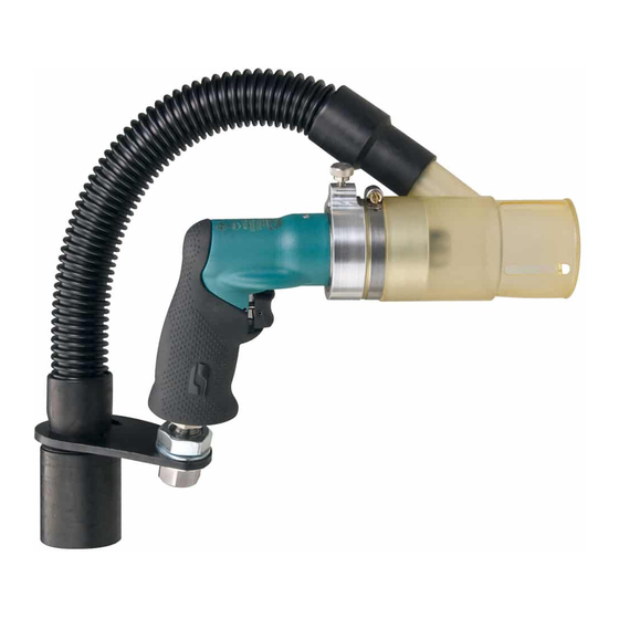
ドリル Dynabrade 52907のPDF 安全、操作、メンテナンスをオンラインで閲覧またはダウンロードできます。Dynabrade 52907 9 ページ。 .4 hp vacuum drill; pistol grip / central vacuum / rear exhaust

Disassembly/Assembly Instructions – Vacuum Pistol Grip Drills
Important: The Dynabrade Pneumatic Power Tool Lifetime Warranty Policy does NOT cover normally wearable parts and products.
Before servicing this tool please contact Dynabrade Inc. or a Dynabrade Subsidiary for information regarding the Dynabrade Pneumatic Power
Tool Lifetime Warranty Policy.
Notice: Special repair tooling referred to in these instructions can be ordered from Dynabrade. (See Page 6)
Disconnect tool from the air supply before servicing.
Tool Disassembly:
For All Models:
1. Use the 96453 Open-end Wrench (16 mm) and a hex key wrench secured into the jaws of the drill chuck. Remove the drill chuck turning it
counterclockwise.
2. Carefully secure the tool in a vise with aluminum or bronze jaws so that the spindle is pointing up. To avoid damaging the housing, do not over
tighten the vise.
3. Use an adjustable wrench to remove the 52852/52853 Nose Cover by turning it counterclockwise.
4. Use the 96453 Open-end Wrench (16 mm) and a 3/16" hex key to remove the 52954 Spindle Nut turning it counterclockwise.
5. Push the spindle out of the 01139 Bearing.
6. Use the 96232 Arbor Press and 96346 Bearing Separator (2") to remove the 02698 Bearing from the spindle.
7. Remove the 97922 Wave Spring from the nose cover.
8. Use internal retaining ring pliers to remove the 97445 Retaining Ring.
9. To remove the 01139 Bearing from the nose cover use the arbor press and the 96241 Bearing Press Tool. (Place the press tool against the inside
race of the bearing.)
For Models: 52903/04/05/06/07
10. Use external retaining ring pliers to remove the 97443 Retaining Ring.
11. Use a 1/8" diameter drive punch to remove the 54472 Pin (3) and 06213 Gear (3) from the carrier spindle. Note: Follow similar disassembly procedure
for models with double planetary gear reduction.
12. Use a 2 mm hex key to remove the 50784 Set Screw from the housing.
For All Models:
13. Use needle nose pliers to remove the spacer or ring gear.
14. Tap rim of housing against a wood block to remove the air motor.
15. Carefully secure the housing in a vise with aluminum or bronze jaws so that the air inlet is pointing up. To avoid damaging the housing,
do not over tighten the vise.
16. Use a 19 mm socket and wrench to remove the inlet bushing turning it counterclockwise. Remove muffler parts.
17. Use a 3/32" diameter drive punch to remove the 50936 Pin and 52955 Trigger Assembly. Remove pin from right side of housing to left side.
18. Secure the hex portion of the air inlet bushing in a vise with aluminum or bronze jaws and use an adjustable wrench to access the valve
assembly parts turning counterclockwise.
Tool Disassembly Complete:
Motor Disassembly:
1. Secure the 96346 Bearing Separator (2") around the end of the cylinder nearest the rear bearing plate. Place the separator on the table
of the 96232 Arbor Press so that the front of the motor is pointing down.
2. Use a 5/32" diameter flat end drive punch as a press tool and push the rotor out of the 02696 Bearing.
3. Remove vanes from the rotor.
4. Use the arbor press and separator to remove the front bearing, plate and spacer from the rotor.
5. Remove the 02696 Bearing from the rear bearing plate with the 96210 Bearing Removal Tool and the arbor press.
Motor Disassembly Complete:
Important: Clean and inspect all parts before assembling.
Motor Assembly:
1. Install 01479 Spacer onto the rotor.
2. Install .003" thickness of shims into 02038 Front Bearing Plate. Install 02649 Bearing into the front bearing plate.
3. Use the 96240 Bearing Press Tool and arbor press to install the front bearing plate along with 02649 Bearing onto the rotor. (Place the press tool
against the inside race of the bearing.)
4. Use a .001" feeler gauge to check clearance between the front of the rotor and the front bearing plate. That clearance must be .001"- .0015". If it is
necessary to adjust the clearance, do this by adding or removing the appropriate shim thickness.
5. Apply Dynabrade Air Lube 95842 to the 01480 Vanes (4) and install these into the rotor slots.
6. Install the 01476 Cylinder so that the air inlet passage lines up with the air inlet holes in the rear bearing plate.
7. Use the 96242 Bearing Press Tool and arbor press to install the 02696 Bearing into the 02673 Rear Bearing Plate. (Place press tool against the
outside race of the bearing.)
8. Use the 96242 Bearing Press Tool and arbor press to install the bearing/rear plate onto the rotor. (Place press tool against the inside race of the
bearing.) Important: Carefully press the bearing/rear plate assembly onto the rotor to achieve a snug fit between the bearing plates and the cylinder.
(continued on next page)
5
