- ページ 4
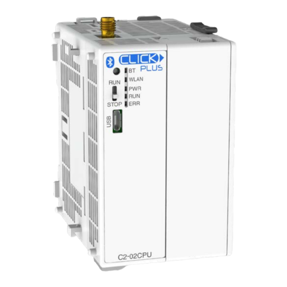
コントローラー Automation Direct CLICK PLUS SeriesのPDF クイック・スタート・マニュアルをオンラインで閲覧またはダウンロードできます。Automation Direct CLICK PLUS Series 11 ページ。

Hardware Installation, continued
CAUTION
Cut off all phases of the power source externally and wait
module or Stackable I/O of a running system.
INSTALL OR REMOVE THE OPTION SLOT MODULE
To install an Option Slot Module
To install an Option Slot Module
To install an Option Slot Module
To install an Option Slot Module
1
Remove the Option Slot Cover (#C2-FILL)
if it was installed in the CPU, by grasping its
top and bottom front corners, squeezing and
pulling it forward.
1
Remove the Option Slot Cover (#C2-FILL)
if it was installed in the CPU, by grasping its
top and bottom front corners, squeezing and
pulling it forward.
2
Hold the
Option Slot
Module by the
top and bottom front
2
corners, align the PCB card
Hold the
edge with the guide slots in the
Option Slot
CPU, and slide the module into
Module by the
its slot. Press the module into place until it is
top and bottom front
fully seated
corners, align the PCB card
edge with the guide slots in the
CPU, and slide the module into
its slot. Press the module into place until it is
fully seated
3
Push the top and bottom locking clips
backward until they click into place.
3
Push the top and bottom locking clips
backward until they click into place.
To remove an Option Slot Module
To remove an Option Slot Module
To remove an Option Slot Module
To remove an Option Slot Module
Lift slightly on the locking clips until they
release, then slide each clip forward.
Reverse the procedure.
Lift slightly on the locking clips until they
release, then slide each clip forward.
Reverse the procedure.
Copyright© 2020, Automationdirect.com Incorporated/All Rights Reserved Worldwide
C2-02CPU Quick Start Guide
5 seconds
before installing or removing the Option Slot
INSTALL OR REMOVE STACKABLE MODULES
1.
Slide the expansion port LOCK lever to "UNLOCK" and
remove bus cover.
2.
Align I/O module with right hand side of CPU, engaging bus
connector so that modules are flush.
3.
Slide the "LOCK" lever firmly towards rear of modules, locking
them together.
3
3
Push the top and bottom locking clips
backward until they click into place.
3
Push the top and bottom locking clips
backward until they click into place.
To remove an Option Slot Module
To remove an Option Slot Module
To remove an Option Slot Module
To remove an Option Slot Module
To remove a module, work the installation steps in reverse.
Lift slightly on the locking clips until they
release, then slide each clip forward.
Reverse the procedure.
INSTALL OR REPLACE THE BATTERY
Lift slightly on the locking clips until they
release, then slide each clip forward.
(Lithium CR2032 battery, Part # D0-MC-BAT, not included)
Reverse the procedure.
1.
Power up the CPU for at least 10 minutes to charge the CPU's
capacitor prior to removing the
battery. This will retain function
memories. We recommend you
backup data memory before
replacing the battery.
2.
Power off the CPU.
3.
Pull out the battery holder. (This
may require a small screwdriver to
push in the tab and lift it when the
unit is mounted.)
4.
Put in a new battery, with the
positive (+) polarity side facing the
battery holder.
5.
Insert the battery holder into the
CPU and push it all the way in.
6.
Power on the CPU.
Battery life is about 3 years. Replace
battery within 10 minutes of power off.
CAUTION
Battery may explode if mistreated.
Do not recharge, disassemble, or dispose of in fire.
www.automationdirect.com/click-plc
3505 HUTCHINSON ROAD
CUMMING, GA 30040-5860
1-800-633-0405
2
1
3
4
5
1
Power 10+ minutes
2
Remove Power
4
