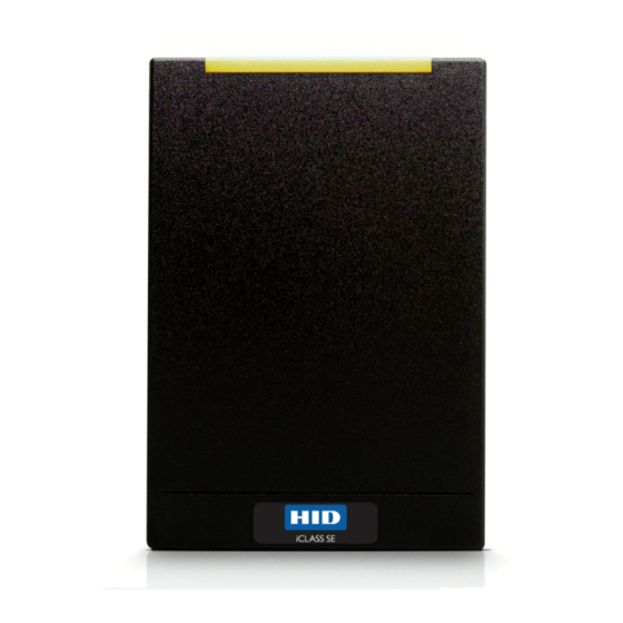
カードリーダー HID RP40MAのPDF インストレーション・マニュアルをオンラインで閲覧またはダウンロードできます。HID RP40MA 2 ページ。 13.56 mhz contactless.
HID RP40MA にも: インストレーション・マニュアル (9 ページ), インストレーション・マニュアル (14 ページ), インストレーション・マニュアル (2 ページ)

INSTA LLATION GUI DE
13.56 MHz Contactless
iCLASS SE® / multiCLASS SE®
R10E, RP10E, R15E, RP15E, R40E, RP40E, RK40E, RPK40E
R10MA, RP10MA, RP15MA, R40MA, RP40MA, RPK40MA
Parts
1 – iCLASS SE/multiCLASSS SE Reader
1 – Installation Guide
2 – #6-32 x .375" Phillips machine screws
3 – #6-32 x .375" spanner security screw
2 – 7-pin Terminal connectors
1 – 10-pin Terminal connector
Specification
BASE PART
PRODUCT
NUMBER
R10
7
900N
900P
RP10
7
900L
R15
910N
910P
RP15
7
910L
R40
920N
7
920P
RP40
7
920L
RK40
921N
921P
RPK40
7
921L
1 Communication protocols other than Wiegand or Clock & Data
(for control panels), as well as credential interfaces over BLE
(not applicable for 9xxL models), require an additional
hardware module which increases current by 40mA.
2 Standby AVG - RMS current draw without a card in the RF field.
3 Maximum AVG - RMS current draw during continuous card reads.
Not evaluated by UL.
BTSmart Specifications
OPERATING TEMPERATURE
-15° to 150° F (-25° to 65° C)
The final product, containing the modular transmitter must be labeled with its own FCC ID and IC ID. If the FCC & IC ID is not visible, when the module
is installed inside another device, then the final assembly label must contain the FCC and IC ID numbers with a statement such as follows: "Contains
Transmitter Module with FCC ID JQ6-ICLASSBTM and IC ID 2236B-ICLASSBTM".
This Installation Guide is for informational purposes only. HID makes no warranties, expressed or implied, in this summary. Company, product names and data used in sample output
are fictitious. Specifications are subject to change without notice.
© 2014 - 2016 HID Global Corporation/ASSA ABLOY AB. All rights reserved. HID, the HID logo, and iCLASS SE are trademarks or registered trademarks of HID Global in the U.S.
and/or other countries. All other trademarks, service marks, and product or service names are trademarks or registered trademarks of their respective owners.
hi dg l o b a l.com
CURRENT
INPUT
VOLTAGE (VDC)
STANDBY
MAX
AVG
2
AVG
60mA
95mA
75mA
100mA
110mA
135mA
60mA
95 mA
5 - 16VDC
75mA
100mA
110mA
135mA
65mA
95mA
85mA
100mA
120mA
145mA
85mA
100mA
5.5 - 16VDC
95mA
105mA
130mA
155mA
4 Peak - highest instantaneous current draw during RF communication.
5 When configured for Bluetooth Operating Range is -13° to 150° F
(-25° to 65° C)
6 Wiegand Cable Lengths:
100 ft (30.5 m) 22 AWG @ 5 - 6.4VDC
500 ft (152 m) 22 AWG @ 6.5 - 16VDC
7 Mobile Enabled Products, see specifications below.
FREQUENCY
2.4 - 2.480 GHz
An ASSA ABLOY Group brand
Recommended
• Cable, 5-9 conductor (Wiegand or Clock-and-Data), 4 conductor Twisted
Pair Over-All Shield and UL approved, Belden3107A or equivalent (OSDP)
• Linear DC power supply
• Metal or plastic junction box
• Security tool (for anti-tamper screw) HID 04-0001-03
• Drill with various bits for mounting hardware
• Mounting hardware
• Reader spacer when mounting on or near metal or metal junction boxes -
see How to Order Guide
• IP65 Mounting gasket, recommended for outdoor installation
• Back box
1
OPERATING
TEMPERATURE
5
PEAK
4
3
Wiegand = 500 ft - 22 AWG (152 m)
200mA
-30° to 150° F
(-35° to 65° C)
220mA
Page 1
PLT-01579 A.4
REGULATORY
CABLE LENGTH
6
REF NUMBER
R10Ex
RP10Ex
Communication Lines
R15Ex
300 ft - 24 AWG 91 m)
RP15Ex
RS-485 = Max bus length
R40Ex
4000 ft - 24 AWG (1,219 m)
Max length between nodes:
RP40Ex
1640 ft - 24 AWG (500m)
RK40Ex
RPK40Ex
UL Reference Number Deciphering
x
Reader Colors:
K = Black
1
x
Wiring:
N = Pigtail
2
T = Terminal
5 = 5 meter Pigtail
x
Communications:
N = No Module
3
R = RS-485 (OSDP)
L = Indala Prox
B = Bluetooth
FCC & IC IDS
FCC-ID: JQ6-ICLASSBTM
IC-ID: 2236B-ICLASSBTM
x
x
1
2
3
x
x
1
2
3
x
x
1
2
3
x
x
1
2
3
x
x
1
2
3
x
x
1
2
3
x
x
1
2
3
x
x
1
2
3
