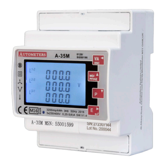
計測機器 Autometers Systems A-35MのPDF クイック・スタート・マニュアルをオンラインで閲覧またはダウンロードできます。Autometers Systems A-35M 2 ページ。

Electrician
The A35M meter should only be installed by a fully qualified electrician who has
knowledge of electricity meters connected with current transformers.
It is the installer who is fully responsible for the safe installation of this meter. It must be
installed to meet the current electrical regulations concerning installation of meters.
EMC Installation Requirements
Whilst this unit complies with all relevant EU EMC (electro-magnetic compatibility)
regulations, any additional precautions necessary to provide proper operation of this and
adjacent equipment will be installation dependent and so the following can only be
general guidance:
Avoid routing wiring to this unit alongside cables and products that are, or could be, a
source of interference.
The supply to the unit should not be subject to excessive interference. In some cases, a
supply line filter may be required.
To protect the product against incorrect operation or permanent damage, surge
transients must be controlled. It is good EMC practice to suppress transients and surges
at the source. The unit has been designed to automatically recover from typical
transients; however in extreme circumstances it may be necessary to temporarily
disconnect the supply for a period of greater than 10 seconds to restore correct
operation.
Screened communication leads are recommended and may be required. These and other
connecting leads may require the fitting of RF suppression components, such as ferrite
absorbers, line filters etc., if RF fields cause problems.
It is good practice to install sensitive electronic instruments that are performing critical
functions in EMC enclosures that protect against electrical interference causing a
disturbance in function.
L
O
A
S1
D
S2
P2
1
2
SHIELD
TX- TX+
+
-
+
S0
RS485
9
10 11
12 13 14
15 16 17 18 19 20
S2
Pulse
Modbus
L3
Voltage inputs
L
1
2
3
4
5
1A FAST BLOW FUSE
AUX
L1
L2
L3
N
Wiring Information
Power Supply
The Auxiliary connection must be connected to power up the meter.
Wiring
Electrical and communication connections are made directly to the front of the meter.
Electrical Connections
2.5mm flexible stranded cable is recommended for all main electrical connections. For the
low voltage communication connections we recommend a twisted shielded cable Belden
9841 2 wire or 9842 4 wire or equivalent.
Phasing and polarity of the AC current and voltage inputs and their relationship is critical to
the correct operation.
S1
M
S2
L1
A
S1
S2
P2
I
L2
N
P2
S
L3
Current inputs
S2 S1
L
S1 S2
S1
S2
S1
L2
L1
O
A
D
P2
IMPORTANT
Current transformer
P1 must face mains
N
L
N
6
7
8
3 PHASE 4 WIRE
1A FAST BLOW FUSE
LOAD
A-35M
METER
Programming the meter
When you receive the meter
there will be at least one value
that you must programme into
the meter. This is the current
transformer ratio.
If the meter has been purchased with the intention of using the RS 485
Modbus output then you will have to program the Modbus parameters you
require. See reverse Communication. (RS 485 Modbus)
Password Entry
To Enter programing mode.
E
Press
Display will show pass
The first digit will flash.
MD
Press
once to increment the number to 1
PF Hz
Press and hold down
P
Press
parameters
Pulse Definition
The pulse outputs can be set to generate pulses to
represent kWh/kVarh
Pulse constant: 0.001/0.01/0.1/1/10/100/1000 kWh or
kVarh per Pulse
Pulse width: 200/100/60 Ms.
The pulse output is passive type, complies with
IEC62053-31 Class A.
ATTENTION: Pulse output must be wired as shown in
the wiring diagram below. Scrupulously respect
polarties and the connection mode. Opto-coupler with
potential-free SPST-No Contact.
Contact range: 5~27VDC Max. current Input: 27mADC
M
A
I
Pulse Output
N
S
This option allows you to configure the pulse output. The
output can be set to provide a pulse for a defined amount
of energy active or reactive. Use this section to set up the
pulse output—Units: kWh, kVArh
From the set-up menu, use
the Pulse output option.
E
Press
to enter the selection routine. The unit symbol will
flash.
MD
Use
and
PF Hz
On completion of the entry procedure, press
the setting and press
Pulse Rate (Energy Value per Pulse)
Pulse rate options: 0.001 , 0.01 , 0.1 , 1, 10, 100, 1000 kWh /
kVarh per Pulse. Default : 0.01 kWh (100imp/kWh)
MD
Use
and
PF Hz
Long press
MD
Use
and
PF Hz
Long press
for 3 seconds
0000
E
to enter program mode.
to scroll down to programme various
OUTPUT
P+
R
U
imp
MD
P
and
buttons to select
PF Hz
P
buttons to choose kWh or kVArh.
E
to confirm
V/A
to return to the main set up menu.
P
to select Pulse Rate option.
E
the setting will flash.
P
to choose Options.
E
for confirmation.
Com
