- ページ 3
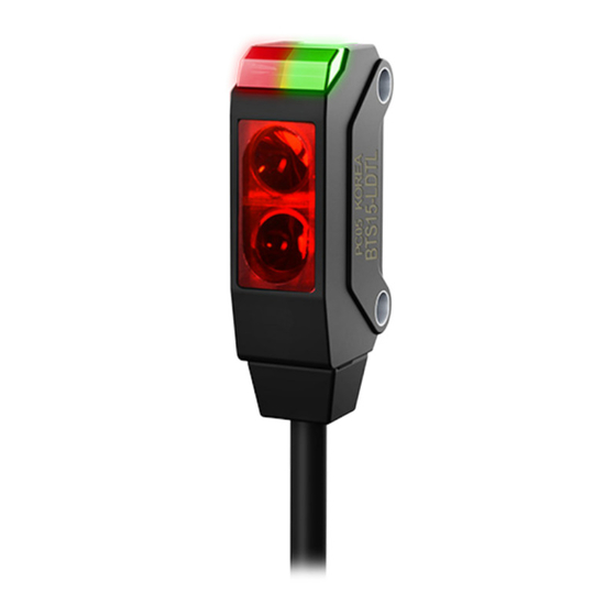
アクセサリー Autonics BTS1M-TDT SeriesのPDF 製品マニュアルをオンラインで閲覧またはダウンロードできます。Autonics BTS1M-TDT Series 4 ページ。 Photoelectric sensors

Specifications
Model
BTS1M-TDT□-□
Sensing type
Through-beam
Sensing distance
1 m
Sensing target
Opaque materials
Min. sensing target
≥ Ø 2 mm
Hysteresis
-
Response time
≤ 1 ms
Light source
Red
Peak emission
650 nm
wavelength
Operation mode
Light ON mode / Dark ON mode model
Indicator
Operation indicator (red), stability indicator (green)
Approval
ᜢ ᜫ
Unit weight (packaged)
≈ 40 g (≈ 65 g)
01) Reflector (MS-6)
02) Non-glossy white paper 50 × 50 mm
03) Sensing distance 100 mm
04) Sensing distance 10 mm
Power supply
12-24 VDCᜡ ±10 % (ripple P-P: ≤ 10%)
Current consumption
It depends on the sensing type
Through-beam
Emitter: ≤ 20 mA, receiver: ≤ 20 mA
Reflective
≤ 20 mA
Control output
NPN open collector output / PNP open collector output model
Load voltage
≤ 26.4 VDCᜡ
Load current
≤ 50 mA
Residual voltage
NPN : ≤ 1 VDCᜡ, PNP : ≤ 2 VDCᜡ
Protection circuit
Reverse power protection circuit, output short overcurrent protection circuit
Insulation resistance
≥ 20 MΩ (500 VDCᜡ megger)
Noise immunity
±240 VDCᜡ the square wave noise (pulse width: 1 ㎲) by the noise simulator
Dielectric strength
1,000 VACᜠ 50/60 Hz for 1 min
1.5 mm double amplitude at frequency of 10 to 55 Hz (for 1 min) in each X, Y, Z
Vibration
direction for 2 hours
Shock
500 m/s² (≈ 50 G) in each X, Y, Z direction for 3 times
Ambient illuminance
Sunlight: ≤ 10,000 lx, incandescent lamp: ≤ 3,000 lx
(receiver)
Ambient temperature
-20 to 55 ℃, storage: -30 to 70 ℃ (no freezing or condensation)
Ambient humidity
35 to 85 %RH, storage: 35 to 85 %RH (no freezing or condensation)
Protection rating
IP67 (IEC standard)
Connection
Cable type
Cable spec.
Ø 2.5 mm, 3-wire (emitter: 2-wire), 2 m
Wire spec.
AWG 28 (0.08 mm, 19-core), insulator outer diameter: Ø 0.9 mm
Material
Case: PBT, sensing part: PMMA, bracket: SUS304, bolt: SWCH10A
BTS200-MDT□-□
BTS□-LDT□-□
Retroreflective
Convergent reflective
5 to 15 mm
5 to 30 mm
10 to 200 mm
01)
02)
02)
≥ Ø 27 mm Opaque
Opaque materials,
materials
translucent materials
≥ Ø 2 mm
≥ Ø 0.15 mm
03)
04)
-
≤ 15 % of sensing distance
ᜢ ᜫ
ᜢ ᜫ
≈ 25 g (≈ 45 g)
≈ 25 g (≈ 45 g)
Sold Separately: Bracket B
• Unit: mm, For the detailed drawings, follow the Autonics website.
1.2
5.2
2.2
6.2
11.2
Sold Separately: Slit for Through-beam Type
■ BTS1M-ST (sticker)
• Unit: mm
6
Ø1
0.2
Applied condition
Min. sensing
Slit Ø
target
Emitter
Receiver
≥ Ø 1.6 mm
Ø 1 mm
○
-
Opaque materials
■ BTS1M-ST-T (SUS Material)
• Unit: mm
7.2
6.8
Ø1
Ø0.5
0.2
7.9
Applied condition
Min. sensing
Slit Ø
target
Emitter
Receiver
○
-
≥ Ø 1.6 mm
Opaque materials
-
○
Ø 1 mm
≥ Ø 1.2 mm
○
○
Opaque materials
○
-
≥ Ø 1.2 mm
Opaque materials
-
○
Ø 0.5 mm
≥ Ø 0.8 mm
○
○
Opaque materials
Feature data ①
1.0
0.8
0.6
0.4
0.2
0
30
20
10
0
10
20
30
Left ← Center → Right
Operation area (mm)
Feature data ③
1.0
0.8
0.6
0.4
0.2
0
30
20
10
0
10
20
30
Left ← Center → Right
Operation area (mm)
3.2
6.7
11.2
• Be sure to attach for the emitter of through-
beam type (packaged unit: 4 pieces).
• Gently wipe the dirt on the lens of the sensor
before using it.
• After attaching the slit, remove the front
protection film.
Max. sensing
distance
500 mm
• This slit is available for the emitter and receiver
of through-beam type
(packaged unit: 2 pieces)
• Ø of slit is depending on the installation
direction.
• After covering the sensor with the slit,
fix them with the bolts and sub-bracket.
Max. sensing
Feature data
distance
500 mm
①
300 mm
②
300 mm
③
100 mm
④
Feature data ②
1.0
0.8
0.6
0.4
0.2
0
30
20
10
0
10
20
30
Left ← Center → Right
Operation area (mm)
Feature data ④
0.14
0.12
0.10
0.08
0.06
0.04
0.02
0
10
5
0
5
10
Left ← Center → Right
Operation area (mm)
