- ページ 3
コントローラー Autonics MD5-HF14 SeriesのPDF 製品マニュアルをオンラインで閲覧またはダウンロードできます。Autonics MD5-HF14 Series 3 ページ。 Micro step 5-phase stepper motor driver
Timing Chart
• The rotation direction is based on facing the shaft, and it is clockwise (CW) when rotating to
the right.
■ 1 pulse input method
[H]
CW
[L]
[H]
CCW
[L]
Rotation
position
CW
■ 2 pulse input method
[H]
CW
[L]
[H]
CCW
[L]
Rotation
position
CW
• Do not input CW, CCW signal at the same time in 2 pulse input method.
It may not operate properly if either of the signal is [H] and another direction signal is input.
I/O Circuit and Connections
+5 VDCᜡ
Signal
1
CW
270 Ω
2
3
CCW
270 Ω
4
5
HOLD OFF
390 Ω
6
7
DIVISION
390 Ω
SELECTION
8
+5 VDCᜡ
2 kΩ
GND
9
ZERO OUT
10 Ω
10
Pentagon
wiring color
BLUE
1
Blue
RED
2
Red
ORANGE
3
Orange
GREEN
4
Green
BLACK
5
Black
• This connection cable color is for Autonics motors,
the color may different when using other motors.
L
Power
100 - 220 VACᜠ
50 / 60 Hz
N
G
GND
01) If the external signal input voltage is exceed the +5 VDCᜡ, connect a resistor at outside.
Troubleshooting
Malfunction
Troubleshooting
Check the connection status between controller and driver and pulse input
When motor does
specifications (voltage, width).
not excite
Check the pulse and direction signal are connected correctly.
When motor
rotates to
When the driver's RUN mode is 1-pulse input method, CCW input [H] is for
the opposite
forward, [L] is for backward.
direction of
When the driver's RUN mode is 2-pulse input method, check CW and CCW
the designated
pulse input are changed.
direction
Check the driver and motor are connected correctly.
When motor
drives unstable
Check the driver pulse input specifications (voltage, width).
CCW
CCW
01)
CW
Operating rotation signal input when 1 pulse input method
Forward rotation signal input when 2 pulse input method
CCW
Rotation direction signal input when 1 pulse input method
([H]: Forward rotation, [L]: Reverse rotation)
Reverse rotation signal input when 2 pulse input method
HOLD OFF
Motor excitation OFF control signal
([H]: Motor excitation OFF)
DIVISION SELECTION
division Selection Signal
([H]: MS2 setting resolution, [L]: MS1 setting resolution)
01)
ZERO OUT
Zero point excitation output signal: ON when Zero point status
Standard
wiring color
Gray+Red
Yellow+Black
Orange+White
Motor
Brown+Green
Blue+Purple
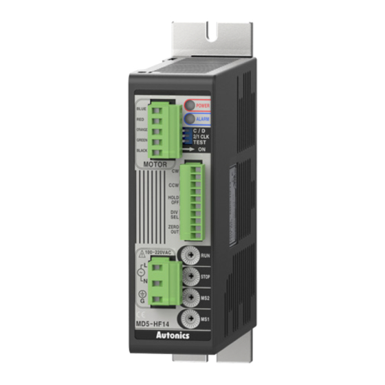
Unit Descriptions
03
04
01
05
06
07
08
02
09
Connections
• In case of standard wiring type, refer to installation method on 5-phase stepper motor.
Motor
User Controller
CW+
CW-
CCW+
CCW-
HOLD OFF+
HOLD OFF-
+
Division selection signal
-
+
Zero point excitation output signal
-
100 - 220 VACᜠ
50 / 60 Hz
18, Bansong-ro 513Beon-gil, Haeundae-gu, Busan, Republic of Korea, 48002
www.autonics.com | +82-2-2048-1577 | [email protected]
01. Motor terminal
02. Power terminal
03. Power indicator
04. Alarm indicator
05. Function selection DIP switch
06. Input terminal
07. RUN current setting rotary switch
08. Stop current setting rotary switch
09. Resolution setting rotary Switch
Blue
Red
Orange
Green
Black
F.G.