- ページ 13
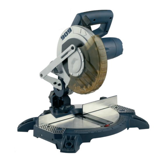
ソウ 909 BN210のPDF 取扱説明書をオンラインで閲覧またはダウンロードできます。909 BN210 16 ページ。 1400w 210mm (8 1/4") compound mitre saw
7. Hold the rotating guard (5)
up and press the spindle
lock button (18). Rotate the
blade until the spindle locks
(Fig. T).
8. Use the 6mm hex key
provided to loosen and
remove the blade bolt.
(Loosen in a clockwise
direction as the blade screw
has a left hand thread)
(Fig. U).
9. Remove the flat washer,
outer blade washer and the
blade (Fig. V).
10. Wipe a drop of oil onto the
inner blade washer and
the outer blade washer
where they contact the blade.
11. Fit the new blade onto the
spindle taking care that
the inner blade washer sits
behind the blade (Fig. W).
CAUTION.
To ensure correct
blade rotation, always install
the blade with the blade teeth
and the arrow printed on the
side of the blade pointing down.
The direction of blade rotation
is also stamped with an arrow on
the upper blade guard.
12. Replace the outer blade
washer.
13. Depress the spindle lock
button and replace the flat
washer and blade bolt.
T
U
V
W
14. Use the 6mm hex key to tighten the blade bolt securely
(tighten in an anti-clockwise direction).
15. Lower the blade guard, hold the rotating lower blade
guard (5) and blade bolt cover (19) in position and
tighten the fixing screw to secure the blade bolt cover in
position.
16. Replace the guard retraction arm (6) and secure onto
the rotating blade guard (5).
17. Check that the blade guard operates correctly and
covers the blade as the saw arm is lowered.
18. Connect the saw to the power supply and run the blade
to make certain that it is operating correctly.
Operation
Cross cut
A crosscut is made by cutting
across the grain of the
workpiece. A 90º crosscut
is made with the mitre table
set at 0º. Mitre crosscuts are
made with the table set at
some angle other than zero
(Fig. X).
1. Pull on the release knob (2)
and lift the saw arm (1) to
its full height.
2. Loosen the mitre locks (15).
3. Rotate the mitre table (12)
until the pointer aligns with
the desired angle.
4. Retighten the mitre locks
(15) (Fig. Y).
13
X
Y