- ページ 5
トランシーバー Galaxy DX-77HMLのPDF オーナーズマニュアルをオンラインで閲覧またはダウンロードできます。Galaxy DX-77HML 10 ページ。 Full channels with +10khz am/fm/usb/lsb/pa mobile transceiver with roger beep
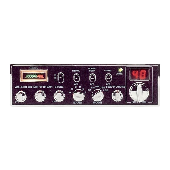
4. RF GAIN CONTROL (outer dual concentric): Use to reduce the gain
of the RF amplifier under strong signal conditions.
5. ECHO (inner dual concentric): This control is used to echo effect.
6. TONE (outer dual concentric): This control is used to intervals of echo
sound.
7. BAND SELECTOR: This switch selects A, B, C, D, E or F of band of
operation.
8. MODE (PA/FM/AM/USB/LSB): This switch is used to select PA, FM,
AAM, LSB or USB mode of operation. Unless the station with which
communication is desired is equipped with SSB, the AM or FM mode is
normally used. The mode selector switch changes the mode of operation
of both transmitter and receiver simultaneously. Turn to "Receiving SSB
signals" for a further explanation of single sideband.
9. CLARIFIER: Allows variation of the receiver operating frequencies
above and below the assigned frequency. Although this control is
intended primarily to tune in SSB signals, it may be used to optimize
AM/FM signals as described in the Operating Procedure paragraphs.
Coarse operates both TX/RX but Fine only in RX.
10. CHANNEL SELECTOR: This switch selects any one of the forty
channels desired. The selected channel appears on the LED readout
directly above the Channel Selector knob.
11. METER: This meter indicates received signal strength, transmitter RF
output power.
12. RF POWER HI-MED-LO: This switch is used to select transmitting
power. In the HI position, the transceiver operates in 7 watts RF output
power. In the MED position, the transceiver operates in 4 watts RF
output power. In the LO position, the transceiver operates in 1 watt RF
output power.
13. OFF/ANL/NB: When the switch is placed in the ANL + NB position,
the RF noise blanker also is activated. The RF noise blanker is very
effective for repetitive impulse nois e such as ignition interference.
14. ROGER BEEP SWITCH: When this switch is placed in the ROGER
BEEP position, your radio automatically transmit the audio sign at the
end of your transmission. The listener can note easily that your
transmission is over through the sign.
- 7 -
15. +10KHz FREQUENCY SHIFT SWITCH. When switch is pressed the
frequency is shifted 10KHz up on following channels. A channel can be
used by setting this switch to +10KHz position.
Normal
3
7
11
15
19
16. RECEIVE/TRANSMIT
INDICATOR:
indicator is located next to the channel indicator. When in receive, the
LED will be green. When in transmit the LED will be red.
17. CHANNEL INDICATOR: Numbered LED indicates the selected
channel you wish to operate on.
+10KHz
3A
7A
11A
15A
19A
The
receive/transmit
LED
- 8 -