- ページ 2
温度コントローラー Autonics TR1D-14CNのPDF マニュアルをオンラインで閲覧またはダウンロードできます。Autonics TR1D-14CN 6 ページ。 Independent single display pid temperature controllers
• When changing the input sensor, turn off the power first before changing.
After changing the input sensor, modify the value of the corresponding parameter.
• Do not overlapping communication line and power line. Use twisted pair wire for
communication line and connect ferrite bead at each end of line to reduce the effect of
external noise.
• Make a required space around the unit for radiation of heat. For accurate temperature
measurement, warm up the unit over 20 min after turning on the power.
• Make sure that power supply voltage reaches to the rated voltage within 2 sec after
supplying power.
• Do not wire to terminals which are not used.
• This unit may be used in the following environments.
- Indoors (in the environment condition rated in 'Specifications')
- Altitude Max. 2,000 m
- Pollution degree 2
- Installation category II
Ordering Information
Model
Control output1 Control output2 Option output
TR1D-14RN
Relay
-
01)
TR1D-14RR
Relay
Relay ↔ Alarm
TR1D-R4RR
Relay
Relay ↔ Alarm
Relay
Relay ↔ Alarm
TR1D-T4RR
TR1D-14CN
Current/SSR
-
01)
Current/SSR ↔
TR1D-14CC
Current/SSR
Transmission
Current/SSR ↔
TR1D-R4CC
Current/SSR
Transmission
Current/SSR ↔
Current/SSR
TR1D-T4CC
Transmission
01) The model does not support terminal for the control output 2 is not available to use heating&cooling control
and alarm outputs at the same time.
02) It is not possible to use dual alarm output and heating&cooling control at the same time.
Product Components
• Product
Manual
For proper use of the product, refer to the manuals and be sure to follow the safety
considerations in the manuals.
Download the manuals from the Autonics website.
Software
Download the installation file and the manuals from the Autonics website.
■ DAQMaster
DAQMaster is comprehensive device management program. It is available for
parameter setting, monitoring.
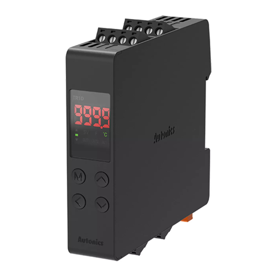
Unit Descriptions
Top terminal
block
5 to 8
1 to 4
01
02
03
Bottom
terminal
block
13 to 16
9 to 12
04
05
Additional
function
-
-
CT input, Dual alarm
-
output
02)
CT input, Dual alarm
Transmission
output
02)
CT input, Dual alarm
Communication
output
02)
-
-
-
CT input
CT input, Dual
Transmission
transmission output
Communication CT input
• Instruction manual
01. PV / SV display part (Red)
RUN mode: Displays PV (Present value)
and SV (Setting value).
Parameter: Displays name and setting
value of parameters.
02. Indicator
Indicator
ON contition
SV
SV display
OUT□
Control output□ ON
AL1
AL1 alarm output ON
The difference between PV and
■
SV is less than 2℃
The difference between PV and
▲/▼
SV is greater than 2℃
'2-2 Temperature unit'
℃ or ℉
parameter setting
03. Control key
[M]: MODE key
[◀] / [▲] / [▼]: Setting value control key
04. PC loader port
Communication converter (Sold
separately) connection
05. Bracket handle
Use to mount and detach the DIN rail.
Specifications
Series
TR1D Series
Power supply
100 - 240 VACᜠ 50/60 Hz
Allowable voltage range
90 to 110% of rated voltage
Power consumption
≤ 8 VA
Sampling period
50, 100, 250 ms
Input specification
Refer to 'Input Type and Using Range'.
• 0.0-50.0 A (primary current measurement range)
Option
CT input
• CT ratio: 1/1,000,
input
• Measurement accuracy: ±5% F.S. ±1digit
relay
250 VACᜠ 3 A 1a
Control
SSR
12 VDCᜡ ±3 V, ≤ 20 mA
output
Current
DC 4-20 mA or DC 0-20 mA (parameter), Load: ≤ 500 Ω
Alarm
AL1, AL2: 250 VACᜠ 3 A 1a
Option
DC4-20 mA (Load resistance: ≤ 500 Ω, Output accuracy: ±0.3%
Transmission
output
F.S.)
RS485 comm.
Modbus RTU / ASCII
Display type
7 segment (red), 4-digit
Control type
ON/OFF, P, PI, PD, PID Control
Control output: 1 to 100 ℃/℉ (0.1 to 100.0 ℃/℉)
Hysteresis
Alarm output: 1 to 100 ℃/℉ (0.1 to 50.0 ℃/℉)
Proportional band (P)
0.1 to 999.9 ℃
Integral time (I)
0 to 9,999 sec
Derivative time (D)
0 to 9,999 sec
Control cycle (T)
Relay output: 0.5 to 120.0 sec, SSR drive output: 0.5 to 120.0 sec
Manual reset
0.0 to 100.0%
Between the power part and the case: 3,000 VACᜠ 50/60 Hz for 1
Dielectric strength
min
0.75 mm amplitude at frequency of 5 to 55Hz (for 1 min) in each X, Y,
Vibration
Z direction for 2 hours
Mechanical
OUT1/2, AL1/2: ≥ 5,000,000 operations
Relay life
OUT1/2, AL1/2: ≥ 100,000 operations (resistance load: 250 VACᜠ
cycle
Electrical
5 A)
Insulation resistance
≥ 100 MΩ (500 VDCᜡ megger)
Double insulation or reinforced insulation (dielectric strength
Insulation type
between the power part and the case: 3 kV)
Square shaped noise (pulse width: 1 ㎲) by noise simulator ±2 kV
Noise immunity
R-phase, S-phase
Memory retention
≈ 10 years (non-volatile semiconductor memory type)
Ambient temperature
-10 to 50 ℃, storage: -20 to 60 ℃ (no freezing or condensation)
Ambient humidity
35 to 85%RH, storage: 35 to 85%RH (no freezing or condensation)
Approval
ᜢ
Unit weight (packaged)
≈ 123.5 g (≈ 194.5 g)
Communication Interface
■ RS485
Communication protocol Modbus RTU / ASCII
Application standard
EIA RS485 compliance with
Maximum connection
31 units (address: 01 to 127)
Synchronous method
Asynchronous
Communication method Two-wire half duplex
Communication
≤ 800 m
effective range
4,800 - 9,600 (default) - 19,200 - 38,400 - 57,600 - 115,200 bps
Communication speed
(parameter)
Response time
5 to 99 ms (default: 20 ms)
Start bit
1 bit (fixed)
Data bit
8 bit (fixed)
Parity bit
None (default), Odd, Even
1 bit, 2 bit (default)
Stop bit
• It is recommended to use Autonics communication converter. Please use twisted pair wire, which is suitable for
RS485 communication.