- ページ 6
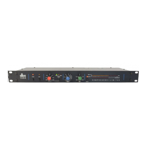
音楽機材 dbx 160AのPDF 取扱説明書をオンラインで閲覧またはダウンロードできます。dbx 160A 20 ページ。 Compressor limiter
dbx 160A にも: パンフレット&スペック (2 ページ)

dbx 160A COMPRESSOR / LIMITER
QUICK SETUP
To get your unit up and running as quickly as possible, do the following steps . For more detailed information, refer to the
specified pages .
• Unpack and Inspect the 160A Package.
• Set Levels and Controls as Needed.
• Connect the 160A to Your System.
INSPECTION
Verify that the 160A package contains the following:
• 160A Unit
• AC Power Cord
• Operation Manual (including Registration Card)
INTRODUCTION
Congratulations on purchasing the dbx 160A Compressor/Limiter. We recommend you take a moment and read through the
manual as it provides information that will assist you from system installation to operation to special applications. Features
include:
• OverEasy®/Hard Knee Selection -- allows selection between our famous OverEasy compression curve and the classic
"Hard Knee" curve popularized by the original dbx 160, 161 and 162.
• True RMS Level Detection™ -- senses the power in the program in a musical manner, much as the ear does, giving
results superior to peak or average detection.
• Hardwire System Bypass Button -- allows the audio to pass even if the unit is unplugged, and is also useful for compar-
ing the processed and unprocessed signal .
• Front Panel SLAVE Button -- couples two 160As together for stereo operation at the push of a button. Note: a 160A unit
cannot be stereo-coupled with a dbx 160XT, 160X, 160, 161 or 162 unit.
• True Power Summing -- When two 160A units are slaved together, the RMS energy of the signal presented to the slave
unit is summed with the RMS energy of the signal presented to the master unit to prevent phase cancellation of the two
signals from causing unmusical compressor action .
• LED Displays -- 19-Segment LED Display for high resolution monitoring of True RMS INPUT and OUTPUT LEVELs;
12-Segment LED Display for GAIN REDUCTION (up to 40dB).
• Meter Calibration -- Input/Output meter calibration, so the 160A can be used in a variety of situations where the "0" ref-
erence is not consistent .
• XLR-type Input and Output Jacks -- because the 3-pin XLR connector has been recognized as the most durable and
widely used connector for professional applications. (An optional output transformer is available.)
• Input and Output Jacks -- with the output capable of driving its own additional 600Ω load (single-ended) in addition to
any load on the XLR output.
• Input Ground Lift Switch -- internally disconnects pin 1 of the input XLR jack from 160A chassis ground to eliminate
any ground loop hum problems that may arise .
• Detector Input -- useful for special applications including frequency conscious compression in which an external equal-
izer is used.
• DC-controlled Parameters -- the signal does not pass through any of the parameter controls. Instead a DC voltage con-
trols all functions; this eliminates any possibility of potentiometer noise developing over time.
2
