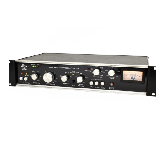
SPECI Fl CATIONS
Input Characteristics
IMP EDANCE
Signa
l
:
22 kohms,
balanced;
11
kohms,
unba lanced
Detector: 600
kohms,
balanced; 300 ko hms, unbalanced
LEVEL
Signal
:
>
+24
dB
(
12.3
V) maxi mum
Detector
:
>
+28 dB
(18.6
V) maximum
Output Characteristic
s
IMP EDANCE
Less than 47
ohms (active low
Z outputl
L
EVEL
>
+23
dBm (1
1
V)
into a
600
ohm or higher
Z
termination
Performance Characteristics
D ISTORTION
2nd harmonic, 0 .05
%
3rd
harmonic,
0 .2% (Auto
or
Manual with Attack
&
Release Controls Centered}
NOTE: Distortion
figures
are
typical
at
infinite compression,
1 kHz, O dBm (0.775 V)
input
and output. 2nd harmonic
is
relatively unaffected by compression ratio, time constants and
frequency while 3rd harmonic decreases with slower time
constants,
higher frequency
and
lower
compression
ratio
.
EQ
U
IVALENT
INPUT NOISE
Less tha
n
-
90dBm, 20 Hz to 20 k Hz
ATTA
CK
RATE*
(63
%
dB
red
ucti on in Signal L evel
}
A uto Mode: 15 mS for 10
dB
level
change, 5 mS for 20 dB
level
change.
3 mS
for
30
dB
level
cha nge
Manual Mode: Continuously
variable
from
1 to 400
dB
per
mi II i second.
RELEAS
E
RATE*
Auto Mode: 120 dB/second
Manual Mode: Conti nuo usly var iab le fro
m
10 to
4000 dB per second.
FREQUENCY
RESPONSE
+O,
-
1
d
B
from 20 Hz to 20 kHz
Controls
THRESHOLD
Conti nuously variab le
from
-
40
dB (7.8
mV}
to+ 10
dB
(2.
4
5 V}
COMPRESSION RATIO
Cont inuously variab
le from
1:
1
to
i
nfinity
:
1
ATTA CK RATE
Continuously
variab le from 400 dB per
mil lisecond
10
1 d
B
per mi
llisecond
R
E
LEASE RATE
Continuously
variable
from
4,000
dB
per
second to
1 0 dB per second
OUTPUT GA
I
N
Continuous ly var
iable
from
-20
dB
10
+20
dB
Metering
RANGE
30 dB (fro
m
-
20 to
+10
VU)
FUNCTION
Switc hab le
for input
level,
output
level
or
gain
change
CALIBRATION
Factor
y
preset
at
O VU
;
+4 dB
(1.23
V}; rear pane
l
potentiometer
sets
O VU for
any level from
-1
0
dB
(7.8
mVI
to
+
10 dB (2.45 V}.
Connectors
SI
G
NAL
Jones type
barrier
strip for
signal input,
signa
l
output,
and
detector
input.
STEREO COUPLER
12
p in
Cinch-Jones J-312 -CCT connector for stra
pp
ing
two 165's
toget
her to process
a
stereo program.
General
POWER REQUIREMENTS
117 V AC + 10%, 50 or 60 Hz; 234 V AC, 50 or 60
Hz
available on special order for
use
outside the U.S.
DIMENSIONS
19" w ide x 3-1
/
2" hig
h
x 10-
1
/
8" deep
(48.3 cm
x
8.9
cm
x 25.
7
cm}; suitab le for rack mounting
NET WEIGHT
8 Pounds
(3.6 kg}
dbx
PRODUCT
WARRANTY
&
FACTORY
SERVICE
All db
x
pr oducts are covered by a lim
it
ed warrant
y.
Consu lt
y
our warranty
card o
r y ou
r
local dealer for fu ll
details.
The dbx Customer Service Depart
ment
is prepared to
give addit ional assis
t
ance in t he use
of
t his prod
uct
. A ll
questions regardi ng in
t
erfac
ing dbx
equi pment w it
h
your
syst
em, service information or infor mation
o
n
special
applic
ations w
il
l be answered. You
may call
d uring
normal business ho urs -
T
elephone:
617 -964-3
210,
Tele
x:
92-25 22, or wri
t
e to
:
dbx
, Inc_
71 Chapel Street
Newton, MA
02195
Attn: Customer Service
Department
Should it become
necessary
to have yo ur equipment
factory serviced:
1. Please repack the
uni
t, includ ing a note describing
the problem along w it
h t
he day, month and year
of
purchase.
2.
Send the unit freigh
t
prepa id to:
dbx, Inc.
224 Calvary Street
Waltham, MA
02154
Attn: Repair Department
3. We recomme nd that yo
u
insure
the package and
send it via
Uni
ted
Parcel
Service whe rever possible.
4
. Please direct all in
qui
ries to db
x
Customer Service
Department
.
Out
side
t
he
U.S.A
. - co ntact you
r
nearest db
x
dealer
for the name and address
of t
he nearest autho
ri
zed
repair center.
•Measured in the infinite
compression
region of the over easy curve.
10
