- ページ 2
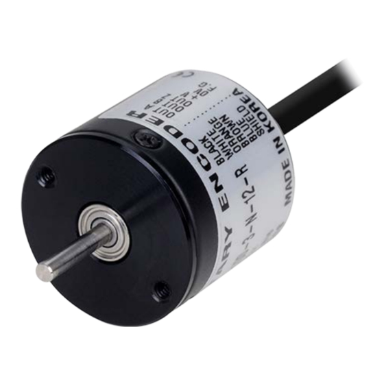
メディア・コンバーター Autonics E20 3-V SeriesのPDF 製品マニュアルをオンラインで閲覧またはダウンロードできます。Autonics E20 3-V Series 3 ページ。 Incremental rotary encoder

Cautions during Installation
• Install the unit correctly with the usage environment, location, and the designated
specifications.
• Do not load overweight on the shaft.
• Do not put strong impact when insert a coupling into shaft.
Failure to follow this instruction may result in product damage.
• When fixing the product or coupling with a wrench, tighten under 0.15 N m.
• If the coupling error (parallel misalignment, angular misalignment) between the shaft
increases while installation, the life cycle of the coupling and the encoder can be
shorten.
• Do not apply tensile strength over 15 N to the cable.
Ordering Information
This is only for reference, the actual prodcut does not support all combinations.
For selecting the specified model, follow the Autonics website.
E20
❶
❷
-
❸
❶ Shaft type
S: Shaft type
HB: Hollow Built-in type
❷ Shaft outer diameter /
Shaft inner diameter
2: Ø 2 mm
2.5: Ø 2.5 mm
3: Ø 3 mm
❸ Resolution
Number: Refer to resolution in
'Specifications'
❹ Output phase
3: A, B, Z
6: A, A, B, B, Z, Z
Product Components
Shaft type
Shaft type
Product Components
Product, Instruction manual
Bolt
× 4
Coupling
× 1
Bracket
-
Connections
• Unused wires must be insulated.
• The metal case and shield cable of encoders must be grounded (F.G.).
• F.G. (Frame Ground) must be grounded separately.
■ NPN open collector /
Voltage output
Color
Function Color
Function
Black
OUT A
Brown
+V
White
OUT B
Blue
GND
Orange
OUT Z
Shield
F.G.
Inner Circuit
• Output circuits are identical for all output phase.
■ NPN open collector output
LOAD
Max. 30 mA
■ Line driver output
A
A
-
❹
-
❺
-
❻
❺ Control output
N: NPN open collector output
V: Voltage output
L: Line driver output
❻ Power supply
5: 5 VDCᜡ ±5%
12: 12 VDCᜡ ±5%
❼ Connection
R: Axial cable type
S: Radial cable type
Hollow Built-in type
× 2
-
× 1
■ Line driver output
Color
Function Color
Black
OUT A
Orange
Red
OUT A
Yellow
White
OUT B
Brown
Gray
OUT B
Blue
Shield
F.G.
-
■ Voltage output
Max. 10 mA
LOAD
Output Waveform
• The rotation direction is based on facing the shaft, and it is clockwise (CW) when
rotating to the right.
• Phase difference between A and B:
■ NPN open collector /
Voltage output
T
T
T
±
2
4
H
A
L
T
T
±
4
8
H
B
L
T±
H
Z
L
-
❼
clockwise (CW)
Specifications
Model
Resolution
Control output
Output phase
Inflow current
Residual voltage
Outflow current
Output voltage
Response speed
01)
Max. response
frequency
Max. allowable
revolution
02)
Starting torque
Inertia moment
Allowable shaft
load
Unit weight
Approval
01) Based on cable length: 1 m, I sink: 20 mA
02) Select resolution to satisfy Max. allowable revolution ≥ Max. response revolution
[max. response revolution (rpm) =
Model
Power supply
Function
OUT Z
Current
consumption
OUT Z
Insulation
+V
resistance
GND
Dielectric strength Between all terminals and case: 500 VACᜠ 50 / 60 Hz for 1 minute
Vibration
Shock
Ambient temp.
Ambient humi.
Protection rating IP50 (IEC standard)
Connection
Cable spec.
T
T
±
(T = 1 cycle of A)
4
8
■ Line driver output
H
A
L
H
A
L
H
B
T
L
2
H
B
L
H
Z
L
H
Z
L
E20□□-□-3-N-□-□
E20□□-□-3-V-□-□
100 / 200 / 320 / 360 PPR model
NPN open collector
Voltage output
output
A, B, Z
A, B, Z
≤ 30 mA
-
≤ 0.4 VDCᜡ
≤ 0.4 VDCᜡ
-
≤ 10 mA
-
-
≤ 1 ㎲
100 kHz
6,000 rpm
≤ 5 × 10
N m
-4
≤ 0.5 g·cm
(5 × 10
kg·m
)
2
-8
2
Radial: ≤ 200 gf, Thrust: ≤ 200 gf
≈ 35 g
ᜢ ᜫ
ᜢ ᜫ
max. response frequency
× 60 sec
resolution
E20□□-□-3-N-□-□
E20□□-□-3-V-□-□
5 VDCᜡ ± 5% (ripple P-P: ≤ 5%) /
12 VDCᜡ ± 5% (ripple P-P: ≤ 5%) model
≤ 60 mA (no load)
Between all terminals and case: ≥ 100 MΩ (500 VDCᜡ megger)
1 mm double amplitude at frequency 10 to 55 Hz (for 1 minute) in each X, Y,
Z direction for 2 hours
≲ 50 G
-10 to 70 ℃, storage: -20 to 80 ℃ (no freezing or condensation)
35 to 85%RH, storage: 35 to 90%RH (no freezing or condensation)
Axial / Radial cable type model
Ø 3 mm, 5-wire (Line driver output: 8-wire), 1 m, shield cable
T
T
T
±
4
2
T
T
±
8
4
T
T±
2
clockwise (CW)
E20□□-□-6-L-5-□
Line driver output
A, A, B, B, Z, Z
≤ 20 mA
≤ 0.5 VDCᜡ
≤ -20 mA
≥ 2.5 VDCᜡ
≤ 0.5 ㎲
ᜫ
]
E20□□-□-6-L-5-□
5 VDCᜡ ± 5%
(ripple P-P: ≤ 5%)
≤ 50 mA (no load)
