- ページ 12
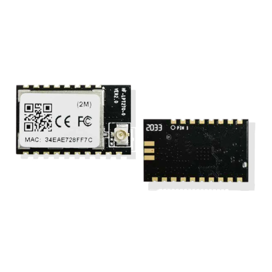
無線モジュール High-Flying HF-LPT270のPDF ユーザーマニュアルをオンラインで閲覧またはダウンロードできます。High-Flying HF-LPT270 18 ページ。 Low power wi-fi + ble module
High-Flying HF-LPT270 にも: ユーザーマニュアル (19 ページ)

HF-LPT270 Series Wi-Fi&BLE User Manual
1.2.4. On-board Chip Antenna
HF modules support internal on-board chip antenna option. When customer select internal antenna,
you shall comply with following antenna design rules and module location suggestions:
For customer PCB, module antenna area can't put componet or paste GND net;(See the
following red arrow area)
Antenna must away from metal or high components at least 10mm;
Antenna can't be shieldedby any meal enclosure; All cover, include plastic, shall away from
antenna at least 10mm;
High-Flying suggest module better locate in following region at customer board, which to reduce the
effect to antenna and wireless signal, and better consult High-Flying technical people when you
structure your module placement and PCB layout.
1.2.5. External Antenna
HF-LPT270-0(F) module supports external antenna(I-PEX) option for user dedicated application.
If user select external antenna,HF-LPT270-0(F) Wi-Fi modules must be connected to the 2.4G
antenna according to IEEE 802.11b/g/n standards. We can provide external antenna if needed.
Contact with our salesman.
Shanghai High-Flying Electronics Technology Co., Ltd(www.hi-flying.com)
Figure 4.
Suggested Module Placement Region
- 12 -
