- ページ 2
スイッチ HighSecLabs Mini-Matrix SX42PH-4のPDF クイック・インストール・マニュアルをオンラインで閲覧またはダウンロードできます。HighSecLabs Mini-Matrix SX42PH-4 3 ページ。 4/8 ports high security mini-matrix kvm switches
HighSecLabs Mini-Matrix SX42PH-4 にも: クイック・インストール・マニュアル (2 ページ)

Installation:
•
Verify that all peripherals and
computers are turned OFF prior to
connecting them to the product.
•
Connect the computers and peripherals
to the HSL Mini-Matrix as shown in the
above diagram.
•
It is possible to connect an HSL AFP
(remote control) to the RDC port of
these devices. Please refer to the AFP
datasheet on how to connect it.
•
Power ON the monitors and the PCs:
Make sure that the monitors are turned
ON prior to powering ON the Mini-
Matrix
•
Power ON the system: Power ON the
KVM by plugging it to the AC wall outlet.
By default, after product power-up, the
active channel will be computer #1
•
NOTE : HSL devices covered by this
manual include a special DP/HDMI
connector, enabling the user to use the
product with both video formats as
input and output.
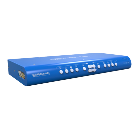
Front Panel LEDs Index:
1.
Active Channel LED indicator
2.
Left/Right Keyboard/Mouse control
LEDs
3.
Left/Right fUSB freeze LED indicators
4.
Left/Right audio freeze LED indicators
5.
Keyboard LEDs for Num/CAPS/SCRL
locks
Mini-Matrix Front Panel/Rear
Panel LED Indications:
The HSL Mini-Matrix has several indications on
its front and rear panels:
EDID LED (rear panel):
•
Off – no EDID
•
Flicker – EDID read in progress
•
On – EDID received
Note: EDID is only read in the first few seconds
of device boot. The secure switch does not
support hot plug or swap of display while
working. in every swap of display it is
recommended to restart the KVM.
©2019 All rights reserved. HSL logo and product names are trademarks or service trademarks of HighSecLabs Ltd (HSL).
All other marks are the property of their respective owners. Images for demonstration purposes only.
SX42PH-4 SX42PHU-4 SX82PH-4 SX82PHU-4
NOTE : In models supporting fUSB, it is
possible to connect additional USB devices
and use them on the host PCs. By default,
authentication devices such as CAC readers,
smart card readers, and biometric readers
are enabled. It is possible to enable other
USB devices. Please refer to HSL's
administrator manual on how to enable
additional USB devices.
Using the HSL Mini-Matrix:
Control of the HSL Mini-Matrix is done,
primarily, using the illuminated push buttons
on the product front panel.
•
Display association: Users can control
which of the connected PCs is projected
on either the left or right display, using
the right and left channel select buttons
accordingly.
•
The HID devices: (mouse and
keyboard), audio, and fUSB (when
applicable) are controlled by the central
control keys. The user has complete
flexibility regarding which computers to
project and to control including viewing
the same PC on both displays.
By default the HID devices will follow
the display association.
fUSB LED:
•
Off – no device detected
•
Flicker – device rejected
•
On- device approved
HID LED:
•
Off – no device detected
•
Flicker – device rejected
•
On- device approved
| QUICK INSTALLATION GUIDE
•
Cursor Navigation: The second mode of
operation is by using CNS (cursor
navigation switching) in which users can
move their HID devices between the left
and right display, using mouse
movement. This function is enabled by
default and requires the user to press
and hold the CTRL key, while dragging
the mouse between the left and right
display (changing control between the
left and right projected PC).
EDID Acquisition
When using the HSL Mini-Matrix, it is
assumed that both connected displays are
the same or use the same native resolution.
EDID is acquired from the left display only
and duplicated to all channels.
If the two displays are not the same, place
the display with the lower native resolution
on the left display console port.
Important Notes:
1. Anti-Tampering System: This HSL high
security product is equipped with an always-on
active anti-tampering system. If mechanical
intrusion is detected, the product is
permanently disabled and abnormal LED
behavior is activated, with all LEDs blinking
continuously.
2. Power ON Self-Test Procedure: As the
product powers-up, it performs a self-test
procedure. In case of self- test failure for any
reason, including jammed buttons, the product
is inoperable and self-test failure is indicated by
abnormal LED behavior.
In the above-mentioned cases, please call
Technical Support and avoid using the product.
For further information please refer to the
product administrator and setup guides.
HDC19961 Rev.1.0
