- ページ 2
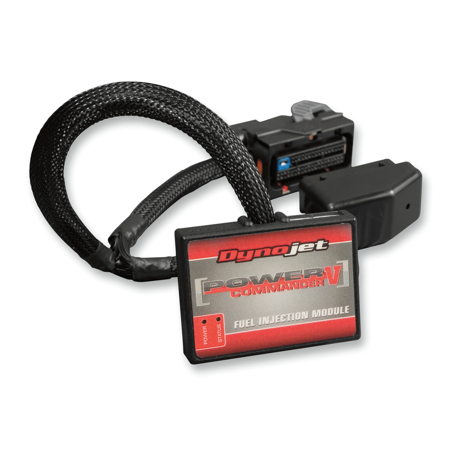
バイクアクセサリー Dynojet Power commander VのPDF 取付説明書をオンラインで閲覧またはダウンロードできます。Dynojet Power commander V 6 ページ。 2017-2018 polaris scrambler 1000, 2017-2018 polaris sportsman 1000
Dynojet Power commander V にも: 取付説明書 (6 ページ), 取付説明書 (9 ページ), 取付説明書 (7 ページ), インストレーション・インストラクション (4 ページ), インストレーション・インストラクション (5 ページ), インストレーション・インストラクション (4 ページ), インストレーション・インストラクション (5 ページ), インストレーション・インストラクション (4 ページ), インストレーション・インストラクション (5 ページ), 取付説明書 (6 ページ), 取付説明書 (6 ページ), インストレーション・インストラクション (5 ページ), 取付説明書 (6 ページ), インストレーション・インストラクション (5 ページ), 取付説明書 (6 ページ), インストレーション・インストラクション (5 ページ), インストレーション・インストラクション (5 ページ), 取付説明書 (7 ページ), インストレーション・インストラクション (5 ページ), インストレーション・インストラクション (4 ページ), 取付説明書 (6 ページ), インストレーション・インストラクション (4 ページ), インストレーション・インストラクション (5 ページ), 取付説明書 (6 ページ), 取付説明書 (8 ページ), インストレーション・インストラクション (4 ページ), 取付説明書 (7 ページ), 取付説明書 (6 ページ), 取付説明書 (8 ページ), インストレーション・インストラクション (4 ページ), 取付説明書 (6 ページ), インストレーション・インストラクション (4 ページ), インストレーション・インストラクション (4 ページ), 取付説明書 (6 ページ), インストレーション・インストラクション (5 ページ), インストレーション・インストラクション (5 ページ), 取付説明書 (6 ページ), 取付説明書 (6 ページ), 取付説明書 (6 ページ), 取付説明書 (7 ページ), 取付説明書 (6 ページ), インストレーション・インストラクション (5 ページ), インストレーション・マニュアル (5 ページ), 取付説明書 (6 ページ), 取付説明書および取扱説明書 (8 ページ), 取付説明書および取扱説明書 (6 ページ), インストレーション・マニュアル (4 ページ), インストレーション・マニュアル (7 ページ), インストレーション・マニュアル (6 ページ), 取付説明書 (6 ページ), インストレーション・インストラクション (5 ページ), インストレーション・インストラクション (5 ページ), 取付説明書 (6 ページ), 取付説明書 (8 ページ), インストレーション・マニュアル (5 ページ), インストレーション・マニュアル (9 ページ), インストレーション・マニュアル (4 ページ), インストレーション・インストラクション (4 ページ), 取付説明書 (6 ページ), 取付説明書 (7 ページ), 取付説明書 (7 ページ), インストレーション・インストラクション (5 ページ), インストール手順 (7 ページ), インストレーション・インストラクション (4 ページ), インストレーション・インストラクション (4 ページ), インストレーション・インストラクション (5 ページ), インストレーション・インストラクション (5 ページ), 取付説明書 (6 ページ), インストレーション・インストラクション (5 ページ), 取付説明書 (5 ページ), 取付説明書 (6 ページ), 取付説明書 (7 ページ), インストレーション・インストラクション (4 ページ), 取付説明書 (7 ページ), インストレーション・インストラクション (5 ページ), インストレーション・インストラクション (4 ページ), インストレーション・インストラクション (4 ページ), インストレーション・インストラクション (4 ページ), インストレーション・インストラクション (5 ページ), インストレーション・インストラクション (5 ページ), インストレーション・インストラクション (5 ページ), インストレーション・インストラクション (4 ページ), インストレーション・インストラクション (5 ページ), インストレーション・インストラクション (4 ページ), インストレーション・インストラクション (4 ページ), インストレーション・マニュアル (6 ページ), インストレーション・インストラクション (4 ページ), インストレーション・インストラクション (5 ページ), 取付説明書 (7 ページ), インストレーション・インストラクション (4 ページ), インストレーション・インストラクション (5 ページ), インストレーション・インストラクション (5 ページ), インストレーション・マニュアル (6 ページ), インストレーション・インストラクション (4 ページ), 取付説明書 (7 ページ), 取付説明書 (6 ページ), インストレーション・インストラクション (4 ページ), 取付説明書 (6 ページ)

