- ページ 6
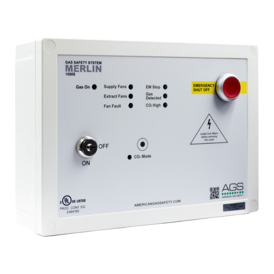
コントロールパネル AGS Merlin 1500SのPDF インストレーション&オペレーションマニュアルをオンラインで閲覧またはダウンロードできます。AGS Merlin 1500S 12 ページ。 Gas & ventilation interlock system
AGS Merlin 1500S にも: ユーザー・インストール・マニュアル (8 ページ), ユーザーマニュアル (12 ページ)

Installation & Operation Manual
Switch Settings
There are various DIP-switches on the front circuit board that can be adjusted to configure your
system as per the following.
Building Management System Integration
There is a DIP-switch located on the circuit board labelled [BMS SEL].
The panel can be integrated with a BMS to make or break a circuit when the gas is either on or
off, (valve open or valve closed). This will tell the BMS whether or not power is being sent to the
solenoid valve.
OFF
Signals the BMS when gas is on or gas is off. (Default)
Signals the BMS on a fault, i.e. high gas levels detected, emergency
ON
shut-off activated, etc.
Fan Switch Integration
There is the facility to connect a Fan Switch.
A fan switch (Merlin FS1 or FS2 - sold separately) provides the facility to turn on fan(s) when the
1500S panel is switched on and removes power to fan(s) when the switched off.
There is a switch located on the circuit board labelled [EM SEL].
Instructs the system to shut down fan(s) and gas supply upon
OFF
activation of emergency shut off button(s). (Default)
Instructs the system to leave the fans on and shut off the gas supply
ON
only upon activation of emergency shut off button(s).
This option is not available if a Fan Switch is not installed.
Fire Panel Integration
The Merlin 1500S can be integrated with a fire alarm to close the gas supply automatically in
the event of a fire. The volt free fire alarm signal can be wired in series with any remote
emergency shut off buttons.
If there are no remote emergency shut off buttons being installed, wire this directly to the
terminal marked [EM REMOTE].
1500S IOM Rev: 08
01-20
Merlin 1500S
6
