- ページ 4
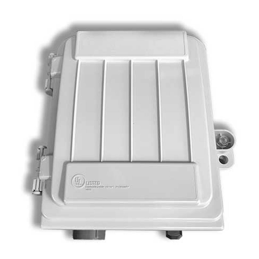
エンクロージャー AFL OptiNID 500のPDF 取付説明書をオンラインで閲覧またはダウンロードできます。AFL OptiNID 500 8 ページ。 Optical demarcation closure

CABLE PREPARATION
Caution: Fiber optic cable is susceptible to damage from excessive bending, pulling or crushing forces.
At every stage of the installation process ensure that the loose buffer tubes or ribbon fibers are free from
unintentional cuts, knick or bends to avoid potential fiber damage.
1. Mark the cable to have a 26" (66.0cm) opening.
2. Use accepted local practice to remove the cable sheath.
Note: If grounding is required, mark and cut the tone wire to 6" (15.3cm) from the sheath opening.
3. Use wire cutters to cut the central strength member (CSM) back at the cable sheath.
4. Mark the buffer tube to have a 22" (56.0cm) opening.
5. Use accepted local practice to remove the buffer tube and clean the fiber.
CABLE INSTALLATION
The OPN-500 comes standard with three cable entry
ports located at the bottom of the closures. Based on the
application needs these ports will accept both NPT conduit
fittings and compression fittings.
Caution: In order to avoid micro bends or fiber
damage do not over-tighten the tie wraps around
the fiber bundles.
1. For application that utilized the Compression Fitting
Kit, determine the appropriate compression fitting for
the application.
2. Install the compression fitting, reference the
Compression Fitting Installation section of this
document.
3. Secure the cable to the retention bracket using
a tie wrap. (Figure 2)
4. Use accepted local practice to ground the tone wire to
the grounding stud located at the bottom left side of the
closure. A common ground will be established.
5. Route the buffer tube into the splice tray.
4" (10.2 cm)
Cable Sheath
INSTALLATION INSTRUCTIONS
OptiNID
26" (66.0 cm)
© 2017, AFL, all rights reserved. Revision A, 2.16.2017
Specifications are subject to change without notice.
4
500 Optical Demarcation Closure
®
Figure 2
