- ページ 16
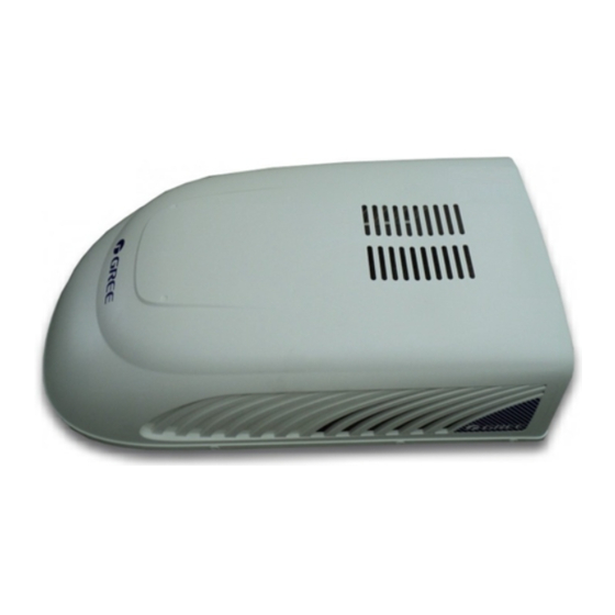
エアコン Gree RVA-135RHPのPDF 取扱説明書 操作と設置をオンラインで閲覧またはダウンロードできます。Gree RVA-135RHP 20 ページ。 Recreational vehicle air conditioner

- 1. Air Conditioner
- 1. 1 A few Words about Your New Air Conditioning Unit
- 1. Electrical Data
- 2. Table of Contents
- 2. 2 Electric Diagram
- 3. 3 Packing List
- 4. 4 Specifications
- 5. 5 Operation of Wireless Remote Control
- 6. 6 Control Panel
- 7. 7 Installation Instruction
- 7. Step 1-Selecting an Installation Location & Installing the Roof Top Air Conditioner
- 7. Step 2-Installing the Ceiling Assembly
- 7. Step 3-Electrical Wiring
- 7. Step 4-Completing the Installation
- 8. 8 Troubleshooting Guide
- 9. 9 Normal Maintenance Procedures
ROUTING 115V AC WIRING
Make sure that all power supply to the unit is disconnected before performing any work on the
unit to avoid the possibility of shock or injury and/or damage to the equipment. After the interior
ceiling assembly frame is properly secured to the roof top air conditioner, the following electrical
connections must be performed.
Frame
Figure 7
Power Cord
Ground Wire
Come From Roof
(Green Wire)
Top Air
Conditioner
Strain
Relief
(Clamp)
Black Wire
Figure 8
Clamp
STEP 3-ELECTRICAL WIRING
Junction Box
Cover
2 Screws
Power Supply
Cord
White Wire
(Clamp)
Control Line Comes
From Roof Top Air
Conditioner
Display Box
of Ceiling
Assembly
Connector
Figure 9
WARNING
!
1.
Route a copper ,with ground, supply wiring
with minimum #12AWG for both 13.5KBtu/h
and 15KBtu/h unit, the wiring from its power
source to the junction box. Do not attach
them at this time.
2.
Take the roof top air conditioner power cord
to connect to the side of the junction box.
3.
Remove the junction box cover (2 screws).
Take the power cord and make it get into the
box through the strain relief that is provided
(see Figure 7).
4.
Connect the power cord to the black,white
and ground wires found in the junction box
with a terminal board. CAUTION Connect black
wire to black wire,white wire to white wire
and the ground wire to earth.(see Figure 8).
Strain
5.
Relief
Tighten the strain relief clamp to secure the
supply power cord.DO NOT OVERTIGHTEN.
Reinstall the junction box cover.
6.
Connect the two connector and secure the
clamp (see Figure 9 and Figure 9-1).
- 14 -
Two connector
(white to white,black to black)
Clamp
Figure 9-1
