- ページ 2
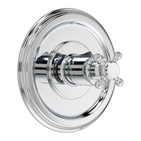
バスルーム設備 JADO Classic 853536.144のPDF インストレーション・インストラクションをオンラインで閲覧またはダウンロードできます。JADO Classic 853536.144 2 ページ。 Pressure balanced shower valve trim kit
TOOLS REQUIRED
Channel Locks
Tubing Cutter
Adjustable Wrench
ROUGHING-IN DIMENSIONS
For reference
1-5/8" TO 3-1/4"
FINISHED WALL
1/2" NPT
OPTIONAL TO
FINISHED FLOOR
USUALLY BETWEEN
72'' AND 84"
"SEE ILLUSTRATION"
SHW
7-7/8"
TUB
48" TO 54"
OPTIONAL
1/2" PLUG
BOTTOM OF
TUB
OR SHOWER
STALL
1
INSTALL TRIM
CAUTION
Turn off water at main supply.
Push CAP (1) onto VALVE CARTRIDGE (2). Secure CAP (1) to
VALVE CARTRIDGE (2) with SCREW (3) for LEVER HANDLE only.
(Spline in CAP (1) must fully engage spline on cartridge stem).
Mount ESCUTCHEON (5) with gasket to valve body and secure
with SCREWS (6).
Push the COVER (7) as shown over the CAP (1) and align
prongs on COVER (7) with screw holes in ESCUTCHEON (5).
Important! Make sure COVER (7) snaps over the SCREWS (6).
1a
INSTALL HANDLE (ADJUST HOT LIMIT STOP
PRIOR TO HANDLE INSTALLATION,
SEE STEP 3)
For Cross Handle: Thread HANDLE BASE (8) onto
threads of CAP (1) until seated against it's internal
stop. With VALVE in off position align CROSS
HANDLE (9) as desired. Install CROSS HANDLE (9)
onto VALVE STEM (15) and tighten HANDLE
SCREW (10). Thread INDEX (11) into
CROSS HANDLE (9).
Lever Handles: Thread HANDLE BASE (4) onto
threads of CAP (1) until seated against it's internal
stop. Install FRICTION WASHER (14) onto base
of LEVER HANDLE (12). Align LEVER HANDLE (12)
and tighten set screw with HEX WRENCH (13)
supplied with faucet to secure handle.
Teflon Tape
Plumbers' Putty or Caulking
INLETS 1/2" NPT
5-7/8"
OUTLETS 1/2" NPT
3-3/8"
THREADED INLETS (STOPS)
1
15
5
3
THREADS
ON CAP
6
7
4
14
8
9
10
13
CROSS HANDLE
11
12
LEVER HANDLES
2
ADJUST HOT LIMIT STOP (MUST BE DONE PRIOR TO TRIM INSTALLATION)
By restricting HANDLE rotation and limiting the amount of hot water allowed to mix with the cold, the
Phillips Screwdriver
HOT LIMIT SAFETY STOP (1) reduces risk of accidental scalding. To set the maximum hot water
temperature of your faucet, all you need to do is adjust the setting on the HOT LIMIT SAFETY STOP (1).
Remove Handle Assembly and Trim. See above step 1 for reference.
Regular Screwdriver
Turn CARTRIDGE STEM (2) to the OFF position (coldest setting) before making adjustment to HOT
LIMIT STOP (1). Use a flat blade screwdriver to pry free the HOT LIMIT SAFETY STOP (1). Pull
forward and rotate counterclockwise one number to limit hot water temperature.
Use ARROW (3) on CARTRIDGE (4) and NUMBERS (5) on HOT LIMIT STOP (1)
for indication.
2
3
TO GAIN ACCESS TO VALVE FOR SERVICING
Remove Handle and Trim from Valve. See step 1 for reference.
Shut off water supply by either closing off main water supply, or closing off the hot and cold CHECK STOPS on valve, if present.
VALVE LEAKS WHEN SHUT OFF
Remove CARTRIDGE (1) by removing CARTRIDGE SCREWS (2). Remove three SCREWS (3) from FIXATION RING (4) and
pull out PRESSURE BALANCING (5) unit.
Clean SEALS (9) on base of CARTRIDGE (1). Check base of PRESSURE BALANCING UNIT (5) and clean O-RINGS (6). Remove
2
CAPS (7) and check O-RINGS on inside of CAPS (7). Clean inside sealing surfaces of VALVE BODY (8).
Re-assemble PRESSURE BALANCING UNIT (5) and CARTRIDGE (1). Tighten all screws. Turn on water supply and see
above for installing TRIM and HANDLE.
UNABLE TO MAINTAIN CONSTANT TEMPERATURE
Remove PRESSURE BALANCE UNIT (5). Remove CAPS (7) and clean valve thoroughly.
Examine balancing unit and check condition of O-ring on end of piston. Piston should move back and forth. Order Repair
Part M952100-0070 if balancing unit is defective.
Replace CAPS (7) and install PRESSURE BALANCE UNIT (5). Make sure inlets line up with two holes in bottom of casting.
Top flange should butt-up against top of casting.
6
8
1 0 9 4 9 3 A
3
5
1
4
4
(Larger Numbers)
0 1 3 5 7 9 11 13 15
4
LARGE OUTLET
1
5
INLETS
7
5
9
3
2
3
2
HOTTER
(Smaller Numbers)
0 1 3 5 7 9 11 13 15
5
COLDER
1
˚
ROTATE 180
BACK TO BACK INSTALLATION
1 0 9 4 9 3 A